When to invest in LED strobe controllers

LED strobe controllers offer many benefits for applications involving low contrast, motion, mark quality assessment, OCR and ambient lighting issues.
Alan L. Lockard
After many years as an end user designing and installing machine vision inspection systems without adding a strobe controller, it's has become clear that the benefits of LED lighting controllers far outweigh the cost in applications that involve:
• Low contrast
• Inspection and motion
• Bar code grading and mark quality assessment
• Optical character recognition
• Ambient lighting issues
Machine vision applications involving image contrasts below 20% present specific challenges. In such low contrast applications, even the slightest variation in LED output intensity can have a substantial impact on the performance of the inspection system.
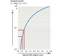
Figure 1: While LED lights are specified as either 12V or 24V, the actual light output from the LED results from current through the semiconductor device. Consequently, all LED device manufacturers specify current control for the most efficient use.
An LED array operating at 100% power generates heat that shortens the life of the LED array, gradually diminishing the output intensity over time. Even with many new LEDs, as they heat up from 25°C - 90°C, the brightness of the LEDs can drop by up to as much as 40%.
This reduction in output intensity may begin manifesting itself by means of false rejects. Eventually, adjustments to either the lighting output or the camera system will be required to restore optimal performance.
A quality LED lighting controller can provide consistently-uniform lighting over the life of the project. For continuous operation, the life of the LED array can be extended by operating at less than 100% power. For strobe control, even when overdriving at lower duty cycle operation, the LED array will last longer.
Operating the LED array at reduced output or in strobed mode reduces heat generation and substantially slows the degradation of LED array output. LED controllers that regulate the current to the LED array rather than the voltage also provide more consistent illumination intensity (Figure 1).
Inspection and motion
In-line machine vision systems tend to be installed on machines where the object being inspected is moving on a conveyor. Depending on the speed of the conveyor, the image will be blurred due to the amount of movement of the object during the exposure period. Factors involved are time (exposure), area (aperture) and intensity (light).
If time is reduced by use of a shorter exposure time to mitigate blur, then either the area or the intensity must be increased for sufficient exposure. While opening the aperture by one f stop doubles the amount of light gathered by the lens, it also reduces the depth of field (DOF) which may be undesirable.
Continuous lighting is limited to what light output is available at 100% power. The only way to increase intensity of continuous lighting is to increase the size and wattage of the LED array. This also increases initial expense, operating costs and produces undesirable heat.
Pulsing or strobing the LED array, especially overdriving it, provides high intensity illumination at short duty cycle. This complements short exposure imaging used for moving objects, and overdriving the array has no detrimental impact on the lifespan or performance of the array (Figure 2).
Barcode grading (verifying) and OCR
Inspection of barcodes at the point of printing helps to ensure reliable readability in the field. Referred to as verifying or grading, there are a variety of recognized standards in use today. All compare numerous physical attributes, each scored individually, and combined into an overall print quality grade.
Attributes such as symbol contrast and modulation are affected by illumination intensity, exposure time and system gain. Once set, exposure time and system gain remain relatively constant in the machine vision camera. However, because LED output degrades over time, only a high-quality LED lighting controller can ensure consistently uniform lighting for the life of the project in such barcode verification applications.
Mark quality assessment at the point of printing the barcode is likely to be on a moving object or surface. Therefore, the steps to mitigate blurring of the moving image mentioned earlier must be considered. Stop action imaging, by combining short exposure time and high intensity strobing, will provide consistent barcode verifying without motion blur that could result in poorer barcode grades. Calibration of the machine vision system for bar code grading can be done using a Calibrated Conformance Standard Test Card.

Figure 2: Converting a constant illumination system to pulse illumination is straightforward. The trigger for the camera is sent to a lighting controller. The controller provides precise pulse width timing, power and brightness control for the lighting pulse. This ensures that the lighting pulses during the camera exposure time and that the light energy is the same for every image.
One application involves a GS1 DataMatrix barcode being printed and verified on webbing moving at 750 inches per minute. The machine vision exposure was fixed at 250μsec to minimize motion blur. Because the GS1-specified minimum resolution is 10 pixels per cell, the working distance was set so that the resolution was approximately 10 pixels per cell.
The LED array was strobed for 1msec at 500%, and the gain of the machine vision sensor was set to 1, then increased incrementally until the Symbol Contrast (SC) measured by the sensor matched the SC recorded on the test target. Making gain adjustments from the bottom up proved more reliable.
This methodology produced an in-line verifier that grades GS1 barcodes in harmony with the benchtop verifier being used by the QC department to verify QC samples. Setting the acceptance criteria on the in-line verifier one letter grade higher than that of the QC benchtop verifier provides a safety margin for print quality degradation caused by subsequent handling and packaging.
The principles just discussed for barcode grading also apply to optical character recognition (OCR). Selecting a quality LED lighting controller and using OCR fonts when printing provide an extremely robust OCR reading application.
Many smart camera-based machine vision systems come with auto-tuned OCR capabilities. These read consistently printed and illuminated images of OCR fonts with a high degree of success. Using a quality LED strobe controller enables consistently reading of 2mm high, low contrast, laser marked, OCR font characters with a high degree of reliability.
Ambient lighting
For a machine vision system to work predictably and accurately on the plant floor, there should be no effects due to ambient lighting. If an inspection is influenced by the operator standing between the overhead lighting and the inspection, there will be problems.
One method of mitigating the effect of ambient lighting is to provide some sort of shrouding over the inspection area to block out ambient light. However, such an approach also obstructs visual inspection of the object.
In pharma and other quality-critical environments, shrouding sections of the production line poses issues with line-clearance procedures. By using high intensity strobing, the influence of ambient lighting on the inspection can be substantially reduced.
With an overdriven LED strobe, the ambient light is literally overpowered. This theory can be easily tested by unplugging the LED array and triggering an inspection. If the inspection image is completely dark, the ambient light is very unlikely to have an impact on the inspection.
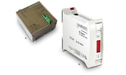
Figure 3: The Gardasoft RT220-20 two channel (left) and RC-120 single channel (right) controllers regulate current to LED lights, provide overdriving capability and are only configurable over Ethernet via embedded web pages to help keep validated settings in their validated state by limiting access.
When using monochromatic machine vision cameras, use of monochromatic LED lighting can also help mitigate the effects of ambient lighting. Choosing the appropriate monochrome LED color is really a matter of what works best with your inspection application. However, once a color is chosen, use of a matching bandpass color filter on the machine vision camera lens limits the impact of the ambient lighting to only the range of the bandpass filter.
Use of a monochromatic LED light source provides a narrow but repeatable imaging scenario for the machine vision system. Reducing as many extrinsic variables of a machine vision system adds to system performance and reliability.
Choice of LED controller
Because these applications were all validated systems, RT220-20 two channel and RC-120 single-channel controllers with Ethernet communications from Gardasoft Vision (Cambridge, UK; www.gardasoft.com) were specified (Figure 3). These controllers regulate the current to the LED light array, provide overdriving capability and are only configurable over Ethernet via embedded web pages, which keeps the validated settings in their validated state by limiting access.
Snippets of program code included with the machine vision smart cameras used provide communication with both the RT and RC controllers. For new "Greenfield Applications" it would be recommended to couple Gardasoft controllers and machine vision cameras that utilize triniti technology. This technology offers tight integration of the machine vision camera and the LED controller.
Whereas the applications mentioned in this article are fixed and unlikely to require reconfiguration over the life of the system, many machine vision applications become part of more flexible automation requiring a recipe-based solution for many different product families. Having such an integrated machine vision camera and lighting configuration will help to meet such demanding applications with greater ease than previous platforms.
This article does not reflect the views or position of the Company but those of the author.
Alan L. Lockard is an Advanced Certified Vision Professional and Principal Engineer in Reagent Engineering at bioMérieux, Inc. (Hazelwood, MO, USA; www.biomerieux.com).