Faster bandwidths and triggering capability added to increased data integrity will cement CoaXPress as the high-speed camera/computer interface of choice.
Andrew Wilson, European Editor
First unveiled ten years ago at the VISION show in Stuttgart, Germany, CoaXPress (CXP) has become the dominant high-speed interface for machine vision cameras and frame grabbers. Originally the standard was developed by a consortium of Adimec (Eindhoven, The Netherlands, www.adimec.com), Eqcologic - now Microchip (Chandler, AZ, USA; www.microchip.com) - Active Silicon (Iver, UK; www.activesilicon.com), Aval Data (Tokyo, Japan; www.avaldata.co.jp), Nippon Electro-Sensory Devices (NED; Osaka, Japan; www.ned-sensor.co.jp) and Components Express Inc (CEI; Woodridge, IL, USA; www.componentsexpress.com).
To date, the CoaXP standard is supported by over 50 vendors of cables, connectors, intellectual property (IP), transceivers, cameras, frame grabbers, simulators, range extenders and software. Many of these can be found on the website of the Japan Industrial Imaging Association (JIIA; Tokyo, Japan; http://jiia.org) and at the CXP website (www.coaxpress.com).
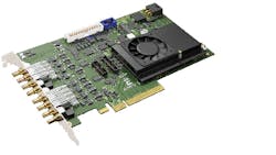
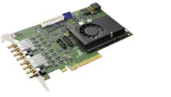
Figure 1: Euresys has announced an eight-channel CXP-6 frame grabber, the Coaxlink Octo, supporting from one to eight CoaXPress cameras, which will be available in the second quarter of this year.
Original rates
As a point-to-point serial camera-to-computer interface, the original version of the standard (and December 2015's revised Version 1.1.1 standard - JIIA CXP-001-2015 - that can be found at: http://bit.ly/VSD-CXP) supports data rates from the camera to the frame grabber of 6.25Gbps over single 75 Ohm coaxial cables. Since CXP is scalable, multiple cables can be used to increase camera to computer bandwidth in increments of 6.25Gbps per channel.
While the high-speed channel is used to transfer data from the camera to the PC, a serial 20.83Mbps frame grabber-to-camera channel is used for I/O (such as camera triggering) and camera control. Up to 13W of power can also be provided over the cable for powering the camera from the frame grabber, host computer or external power supply. Both the 6.25Gbps data channel and 20.83Mbps channel used for triggering and device control use 8b/10b encoding to achieve a DC-balanced signal. "For CXP-6," says Chris Beynon, Chief Technical Officer at Active Silicon, "the 6.25Gbps bit rate equates to a bit period of 1/6.25Gbps or 160ps. Thus, since 8b/10b encoding needs 10bits to send one byte, 1.6ns are required, resulting in a data rate of 1/1.6ns or 625MBytes/s."
"Protocol overhead reduces this data bandwidth, but not significantly. While 1% is used for IDLE words to keep the link locked, a typical packet overhead of 1.5% is added by the packet header and trailer and a fraction more for the image header that provides the image size and format. Thus, in practice, it is safe to use at least 95% of the bandwidth for image data or about 594MBytes/s."
"For the control channel up connection, data is rarely sent. The most important figure is the rate at which a camera can be triggered. This is just under 300kHz if only trigger events are sent, or just under 150kHz if alternating rising and falling triggers are used to allow, for example, the period to control the trigger rate and the pulse width to set the camera's exposure," Beynon explains.
New rates
Version 2.0 of the CXP standard (V2.0) will add two new data rates - CXP-10 (10 Gbps) and CXP-12 (12.5 Gbps) and will double the upconnection speed at those data rates to 41.67 Mbps. "Thus for a single CXP-12 link with FEC and 4k packets, approximately 1.188GBytes/s is achievable," says Beynon. "Similarly, trigger rates will increase to just under 600kHz if only trigger events are sent, or just under 300kHz if alternating rising and falling triggers are used."
"For a 2k packet size with no FEC, the packet overhead is 1.5%," says Martin Cassel of Silicon Software (Mannheim, Germany; https://silicon.software), "while for a 4k packet size this is 0.8%. If FEC is used with these packet sizes the packet overhead increases to 3.3% and 1.8%, respectively," he says.
"FEC will be optional in CXP V2.0 in particular because CXP has an extremely low bit-error rate due to 8b/10b encoding. FEC allows systems to be built when error correction is essential to meet a specification and it may become more relevant as and when an optical interface (which generally seems to be accepted to have a higher bit error rate) is adopted," Active Silicon's Beynon says.
Interfacing cameras
Vendors of camera systems such as Vieworks (Gyeonggi-do, Republic of Korea; www.vieworks.com) have shown products such as the eight (CXP-6) channel VC-12MX2-M/C 330, a 4096 x 3072, 330 fps camera based around the CMV 12000 from CMOSIS (ams Sensors Belgium; Antwerp, Belgium; www.cmosis.com) currently require either eight (CXP-6) channel frame grabbers such as the Komodo CXP frame grabber from Kaya Instruments (Haifa, Israel; www.kayainstruments.com).
Alternatively, the company has demonstrated two quad CXP-6 frame grabbers from Euresys (Angleur, Belgium; www.euresys.com) to run at full speed with the camera (see "CMOS cameras leverage the power of CoaXPress," Vision Systems Design, December 2016, http://bit.ly/VSD-CMOS).
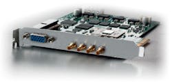
Figure 2: While frame grabbers such as the microEnable 5 marathon VCX-QP from Silicon Software currently support CXP V.1.0, its next generation frame grabbers will support CXP-12 data rates over coax and a CXP fiber interface should such a standard be released. Image courtesy of Silicon Software.
With the introduction of V2.0 of the CXP standard, such a camera would only require four channels, reducing both camera and frame grabber costs. Meanwhile, Euresys has announced an eight-channel CXP-6 frame grabber, the Coaxlink Octo, supporting from one to eight CoaXPress cameras, which will be available in the second quarter of this year (Figure 1).
Although a number of frame grabber companies have announced their intentions to develop products based around the CXP V2.0 standard, these products are many months from completion. Active Silicon, for example, is currently developing a four-channel CXP-12 version with a PCIe Gen3 x8 interface and will also offer single and dual channel versions that will use smaller micro-BNC connectors (Figure 2).
All these will support a high-speed upconnection for triggering and camera control, although the almost 600 kHz standard trigger rate should meet the needs of most applications. While frame grabbers from Silicon Software currently support CXP V.1.0, its next generation frame grabbers will support CXP-12 data rates over coax and a CXP fiber interface should such a standard be released.
Although it has not finalized the specification for its frame grabber, the first offering from Kaya Instruments will be a single-channel CXP-12 implementation with PCIe Gen2 x4 PC interface. According to Marc Damhaut, CEO of Euresys, his company will launch a four-channel Coaxlink CXP-12 frame-grabber in 2018.
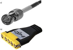
Figure 3: Many different types of cable configurations can be used with both CoaXPress Version 1.0 and 2.0 standards that can include micro-BNC connectors, (a) standard BNC connectors, and (b) CXP-multi-cable connectors that use 75Ω DIN 1.0/2.3 type connectors housed in a single housing. Image courtesy of Components Express Inc.
To support both the 12.5 Gbps (CXP-12) data rate and the 42 Mbps uplink channel, designers of frame grabbers and cameras can choose from two vendors of equalizer and driver circuitry - Microchip and MACOM Technology Solutions (Lowell, MA, USA; www.macom.com). Although Microchip's second generation CXP device, the EQCO125X40, will support CXP-12 data rates and a 42Mbps uplink channel. The same device works as both a cable driver in the camera and an equalizer in the frame grabber. Data has so far been released under non-disclosure agreements (NDA) and many companies have already evaluated-and it seems will use-the parts.
Also under NDA, MACOM has a CXP-12 reference design for both cameras and frame grabbers that use the company's M23428G-33 12G-SDI cable driver and M23544G-14 12G SDI equalizer. The reference design for the camera interface uses the M23428G-33 12G cable driver while the reference circuit for the frame grabber is centered around the M23544G-14 12G equalizer and a low-speed driver. To speed development, the company also offers an evaluation board that includes the reference design for the CXP-12 frame grabber and camera interface.
Help is available too for developers wishing to implement the CXP protocol using FPGAs for such functions as serialization and de-serialization. While many designers will develop custom FPGA code for this purpose, companies such as Demand Creation (Yokohama, Japan; www.dcreation.jp), Easii IC (Grenoble, France; www.easii-ic.com), Kaya Instruments and Sensor to Image (Schongau, Germany; www.s2i.org) all offer developers CXP-compliant cores with which to implement such functions. Sensor to Image, acquired by Euresys in November last year, is working on CoaXPress V2.0 FPGA cores for frame grabbers and cameras, and will continue to offer them to third parties.
Cameras to computers
To connect the camera to the frame grabber, a number of different terminating connectors are available. These include the micro-BNC, which will be the preferred connector for CXP-10 and CXP-12, BNC connectors (Figure 3a), CoaxPress DIN 1.0/2.3 connectors and CXP-multi-cable connectors terminated with male 1.0/2.3 CXP multi-connectors such as those produced by CEI. One implementation of this is a connector from CEI that employs four data channels and one high-speed up-link channel (Figure 3b).
For moving applications requiring high-flex CoaXPress cable assemblies, Intercon 1 (Merrifield, MN, USA; www.intercon-1.com) offers JIIA certified, CoaXPress compliant cables rated for more than 10 million cycles (See http://bit.ly/VSD-IC1).
Using co-ax cable, and depending on the speed of the image data, the CXP standard can support long camera-to-computer distances. At 6.25 Gbps (CXP-6), the maximum cable length is approximately 25m for thin or highly flexible cables and over 200m using thicker cables at 1.25Gbps.
Such distances are dependent on the type of cable used. For example, Microchip specifies that by employing the 7731A Serial Digital Coax from Belden (St Louis, MI, USA; www.belden.com), distances from 58-194m can be achieved depending whether the data rate is CXP-6 (6.25Gbps) or CXP-1 (1.25Gbps), respectively.
Other manufacturers such as Gepco (Richmond, IN, USA; www.gepco.com) specify these distances as between 68-212m at the CXP-6 and CXP-1 data rate using the company's VHD1100 high-definition video coax. "Transceivers for CoaXPress Camera Solutions," compares the performance of different cables from Belden, Canare (Totowa, NJ, USA; www.canare.com) and Gepco: http://bit.ly/VSD-CXP2.
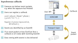
Figure 4: GenICam, a standard that allows industrial camera interfaces to be decoupled from the developer's application programming interface (API), will allow GenICam-compliant event packets from the camera (such as when an exposure has completed) to be sent to the PC. Image courtesy of Basler AG.
Needless to say, longer cable distances result in an increase in signal noise, distortion and jitter. In Version 2.0 of the CXP standard and the increased data rates of 10 Gbps (CXP-10) and 12.5 Gbps (CXP-12) will mean that cable lengths will be reduced although recent improvements in cable equalizers will counter this reduction.
"Cables in the range 5m to 25m cover a very high percentage of vision applications, and coax does this with an excellent balance of cost/power consumption and size," says Benyon.
To accomplish longer camera-to-cable distances, fiber-optic interfaces must be used. However, unlike Camera Link HS that specifies the use of fiber-optic interfaces using SFP and SFP+ connectors to attain distances of over 300m, the specification for a fiber interface in either Version 1.1.1 or Version 2.0 of the CoaXPress standard is still under discussion. In the meantime, external fiber-optic repeaters are required for such applications that may require longer camera-to-computer connections.
Luckily, a number of companies manufacture such repeaters including Kaya Instruments and Phrontier Technologies (Lake Forest, CA, USA; www.phrontier-tech.com). While the CoaXPress Range Extender over Fiber (SFP+) from Kaya Instruments currently supports up to four 6.25Gbps (CXP-6) channels up to 10km maximum distance, the PHORTE 4-channel fiber extender from Phrontier Technologies is also a four-channel 6.25Gbps implementation that extends link distances over fiber to 80km.
Certainly, the introduction of V2.0 of the standard represents an opportunity for vendors who are likely to develop versions of the extenders to accommodate bit rates as fast as 12.5 Gbps (CXP-12).
Although CoaXPress V2.0 may not (yet) have adopted a standard fiber interface standard, it has borrowed from one of the other features present in the Camera Link HS specification: the ability to send images from a single camera to multiple frame grabbers. Such a configuration, for example, facilitates multiprocessing since the same image can then be processed on multiple PCs.
Up until now, this could only be performed using products such as Coaxlink Quad G3 DF frame grabber from Euresys that features four CoaXPress CXP-6 inputs and four data-forwarding outputs and the CoaXPress splitter from Bitflow (Woburn, MA, USA; www.bitflow.com) that can take a CoaXPress signal from a camera and send it to up to four different systems for processing and/or display (see "CXP image splitter replicates data across PCs," Vision Systems Design, July 2016,http://bit.ly/VSD-CXP3).
Software support
CXP V2.0 includes enhanced support for GenICam, the industry-standard generic programming camera interface for machine vision cameras administered by the European Machine Vision Association (EMVA; Barcelona, Spain, www.emva.org). CXPV2.0 will add support for GenICam-compliant event packets to be sent from the camera (such as when an exposure has completed) the PC (Figure 4).
Associated data such as this can then be used by the application software to more easily perform image processing tasks, such as increasing the dynamic range of sequences of images exposured at different times. Companies developing image processing and machine-vision software such as MVTec Software (Munich, Germany; www.mvtec.com), Norpix (Montreal, QC; Canada; www.norpix.com) and Stemmer Imaging (Puchheim, Germany; www.stemmer-imaging.com) are likely to leverage this capability in their software packages.
"Stemmer Imaging's Common Vision Blox (CVB), for example, uses the standard GenICam Transport Layer (GenTL) interface to operate with cameras and frame grabbers," explains Mark Williamson, Director of Corporate Market Development at Stemmer Imaging. "The GenTL Interface provides a mechanism called Events sent by the camera to GenTL Consumers (such as libraries and software packages). Since CVB relies on GenTL Producer implementations from frame grabber and camera vendors, those companies must up support for such new features. A common case for using such an Event is for notifying that the camera's exposure has ended and a robot or other mechanism that may have moved the object being imaged can continue.
"Support for three-dimensional data, however, will not be added to CXP V2.0 because the new GenICam module called GenDC - a Generic Data Container (formerly called GenSP) is being designed to allow any of the transport layers to support any data format from traditional 2D data to 3D to compressed formats," says Active Silicon's Beynon.
"However, this is work in progress and not yet finalized," says Stemmer's Williamson. "The intention of GenDC is to describe a common container format used by various transport layer technologies like CXP and other such as USB3 Vision that can contain 2D images, 2-1/2D data or 3D point cloud data. Additional information such as the coordinate system used to produce this 3D data is then handled through the GenICam node map of the camera."
"Although GenDC will not be ready when CXP 2.0 is released, it will be when CXP 2.1 is announced. Then, by supporting GenDC data, any future image format will be automatically included," concludes Beynon.
Acknowledgement
The author would like to thank Chris Beynon, CTO of Active Silicon, for his help in preparing this article.
Companies mentioned
Active Silicon
Iver, UK
www.activesilicon.com
Adimec
Eindhoven, The Netherlands
www.adimec.com
Aval Data
Tokyo, Japan
www.avaldata.co.jp
Basler
Ahrensburg, Germany
www.baslerweb.com
Belden
St Louis, MI, USA
www.belden.com
Bitflow
Woburn, MA, USA
www.bitflow.com
Canare
Totowa, NJ, USA
www.canare.com
CMOSIS (ams Sensors Belgium)
Antwerp, Belgium
www.cmosis.com
Demand Creation
Yokohama, Japan
www.dcreation.jp
Components Express Inc (CEI)
Woodridge, IL, USA
www.componentsexpress.com
Easii IC
Grenoble, France
www.easii-ic.com
Eqcologic - now Microchip
Chandler, AZ, USA
www.microchip.com
Euresys
Angleur, Belgium
www.euresys.com
European Machine Vision Association (EMVA)
Barcelona, Spain
www.emva.org
Gepco
Richmond, IN, USA
www.gepco.com
Intercon 1
Merrifield, MN, USA
www.intercon-1.com
Kaya Instruments
Haifa, Israel
www.kayainstruments.com
Linköping University
Linköping, Sweden
https://liu.se
MACOM Technology
Solutions
Lowell, MA, USA
www.macom.com
MVTec Software
Munich, Germany
www.mvtec.com
Nippon Electro-Sensory
Devices (NED)
Osaka, Japan
www.ned-sensor.co.jp
Norpix
Montreal, QC, Canada
www.norpix.com
Phrontier Technologies
Lake Forest, CA, USA
www.phrontier-tech.com
Sensor to Image
Schongau, Germany
www.s2i.org
Silicon Software
Mannheim, Germany
https://silicon.software
Stemmer Imaging
Puchheim, Germany
www.stemmer-imaging.com
Vieworks
Gyeonggi-do, Republic of Korea
www.vieworks.com
For more information about machine vision cameras and camera interface products, visit Vision Systems Design's Buyer's Guide buyersguide.vision-systems.com
About the Author
Andy Wilson
Founding Editor
Founding editor of Vision Systems Design. Industry authority and author of thousands of technical articles on image processing, machine vision, and computer science.
B.Sc., Warwick University
Tel: 603-891-9115
Fax: 603-891-9297