Robot-carried vision system inspects engine block surfaces
A robot-carried vision system provides precise and repeatable multi-point surface-quality inspection of engine blocks.
Most of the engine blocks used in automobiles and trucks today are manufactured using a sand casting process that involves pouring molten metal into a sand mold. After the casting process, the engine block is allowed to cool and then further machined to remove any surface defects.
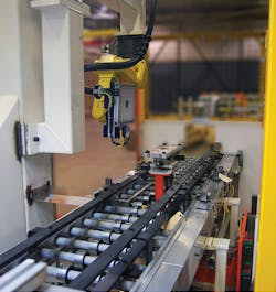
Figure 1: Using a custom automated production line complete with a robot-carried vision inspection system, a major automotive vendor is inspecting engine blocks for defects.
When the machining step is complete, the cylinder block must be inspected to detect any defects in the machined face of the block, such as scratches.
Additionally, the system must ensure the presence of threads in bore holes and coolant passages and detect whether any void or holes (porosity effects) are present due to gases and contaminants present during the casting process.
At the same inspection station, it is also necessary to read any barcodes or alphanumeric data peen-printed or laser marked on the block before it can proceed to the next stage of the assembly process.
This was the task faced by a large automotive manufacturer that supplies engines both to its parent company and other automotive manufacturers. To perform the task of engine block inspection, the company sub-contracted Harry Major Machine (Clinton Township, MI, USA; www.harrymajormachine.com) to build a custom automated production line complete with a robot-carried vision inspection system (Figure 1).
As with many such systems, it is the combination of both mechanical engineering and robot-carried vision that makes such systems unique.
As engine blocks emerge from final machining and onto the system’s conveyor belt, their presence is detected at the vision station by a proximity switch that is interfaced to the plant’s programmable logic controller (PLC).
This PLC, in turn, actuates a rotational lift mechanism (partially shown in red in Figure 1), that lifts the engine block (not shown) above the conveyor.
Since it was not a requirement to perform an inspection on the pan face of the engine block, it was only necessary to inspect the top cylinder head surface and the four surrounding sides of the block. This could have been accomplished using a vision-enabled robot capable of moving around all four sides of the engine block as it sat stationary on the production line. However, to produce a more cost-effective system, Harry Major Machine’s engineers decided that by rotating the engine block through 180°, the same task could be performed with a less expensive LR Mate 200iD from Fanuc (Oshino, Japan; www.fanuc.com).
Automated inspection
To perform automated inspection of the engine block, it was necessary to equip the LR Mate 200iD robot with two camera systems. Since the expertise of Harry Major Machine is building automated production line systems for automotive manufacturers, the company sub-contracted Leoni Engineering Products & Services, Inc. (Lake Orion, MI, USA; www.leoni-americas.com) to perform the task of designing a robot-carried vision system capable of inspecting the engine blocks.
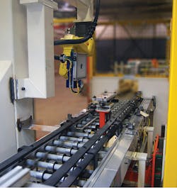
Figure 2: While areas of porosity and the presence/absence of plugs and threads within boreholes can be performed with a camera fitted with a wide field of view (FOV), higher resolution was required to capture images of the barcode and dot-peened alphanumerics embossed on the block. These cameras can be seen fitted to the robot in Figure 1.
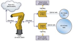
While areas of porosity and the presence/absence of plugs and threads within tapped holes can be performed with a camera fitted with a wide field of view (FOV), higher resolution was required to capture images of the barcode and dot-peened alphanumerics embossed on the block (Figure 2). To image areas for porosity, an In-Sight 7802 smart camera from Cognex (Natick, MA, USA, www.cognex.com) was fitted with an 8.5mm lens from Edmund Optics (Barrington, NJ, USA; www.edmundoptics.com) and mounted to the LR Mate 200iD robot. To highlight any defects on the engine block, a flat diffuse light from Smart Vision Lights (Muskegon, MI, USA; www.smartvisionlights.com) was coupled to the camera. By using this smaller wavelength of light and by coupling the 8.5mm lens to a blue bandpass filter from Midwest Optical Systems (Palatine, IL, USA; www.midopt.com) the contrast of defects such as scratches, as well as any voids and holes on the engine block, could be captured more effectively.
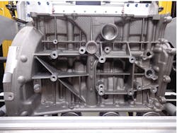
Figure 3: Since the size of the engine block is quite large, the robot-carried vision system is required to traverse a pre-programmed path to capture images of the salient parts that need to be inspected.
To image the laser etched and dot peened marks on the engine block, higher resolution was required. Once again, a Cognex In-Sight 7802 smart camera mounted to the LR Mate 200iD was used to image the code but this was fitted with a 16mm lens from Edmund Optics to obtain the finer detail required. Rather than use a flat diffuse light to illuminate alphanumeric and barcode features, the 16mm lens was fitted with an RM75 blue LED ring light from Smart Vision Lights. This allowed the light to be used in a partial brightfield/darkfield mode such that, once the 16mm lens was fitted with a blue bandpass filter, the contrast of the alphanumeric and 2D barcode became more pronounced.
Robots and vision
In operation, the inspection of both image surfaces, tapped holes, alphanumeric and 2D Data Matrix codes are performed in two stages. After the engine block is lifted into position, images of the top of the engine block and the two nearest sides are captured. After these images are captured, the block is rotated by 180° and images of the remaining two sides are captured. These images are then analyzed in the both the In-Sight 7802 smart cameras using In-Sight Explorer software.
Since the size of the engine block is quite large, the robot-carried vision system is required to traverse a pre-programmed path to capture images of the salient parts that need to be inspected (Figure 3). These include inspecting the surface of the block for scratches and porosity defects, inspecting for threads in the mounting holes, seal plugs and reading the Data Matrix and human readable code stamped on the part. In Figure 3, the seal plug to be inspected can be seen at the center of the image while the alphanumeric and Data Matrix code data can be seen in the upper center.
As the vision system is moved across the face of the block, images are captured by the camera systems. However, it is not necessary to process complete images as only specific areas within the images need to be analyzed.
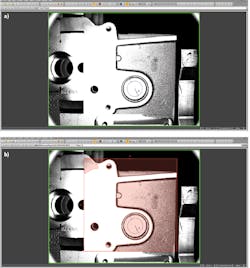
Figure 4: Only part of an image may need to be analyzed for any porosity defects. To accomplish this, the robot is first moved to a specific known location and an area of the engine block is captured (a). Then a pre-programmed mask is used to isolate the area (shown in red) that is required to be inspected (b).
For example, only part of an image may need to be analyzed for any porosity defects. To accomplish this, the robot is first moved to a specific known location and an area of the engine block is first captured (Figure 4a). After this, a pre-programmed mask is used to isolate the area that is required to be inspected (Figure 4b). These areas are pre-programmed manually for each specific engine block, after which the system behaves autonomously.
In Figure 4b, the area to be inspected is shown highlighted in red. To inspect for any porosity defects, the In-Sight 7802 smart camera with an 8.5mm lens and flat diffuse light was used to capture images. Cognex’s In-Sight blob finder tool running on the In-Sight 7802 camera was then used to analyze the image. Similarly, to inspect the part for the presence of threads within the boreholes, Cognex’s PatMax vision tool is used. Reading the alphanumeric and dot peened data was then tasked to the In-Sight 7802 with the 16mm lens and ring light running Cognex’s 2DMax 2D Data Matrix code reader and OCR/OCV tool for reading the alphanumeric data.
Results from the inspection tasks are then transferred over Ethernet to the system’s PLC. When an engine block passes all the inspection tasks, the engine block can then proceed on the conveyor to the next assembly station. Should any defects be found, then the engine block is transferred to a separate station for reworking.
Presently, the system is in operation at the automotive manufacturer where it is being used to detect defects as small as 0.8mm on the machined surfaces of the engine block, and verify the presence of tapped holes and presence of core plugs. With a cycle time of 72 seconds, the system also measures the orientation of bearing caps on the engine block and verifies both the alphanumeric and Data Matrix code on the block.
Companies mentioned:
Cognex
Natick, MA, USA
www.cognex.com
Edmund Optics
Barrington, NJ, USA
www.edmundoptics.com
Fanuc
Oshino, Japan
www.fanuc.com
Harry Major Machine
Clinton Township, MI, USA
www.harrymajormachine.com
Leoni Engineering Products & Services, Inc.
Lake Orion, MI, USA
www.leoni-americas.com
Midwest Optical Systems
Palatine, IL, USA
www.midopt.com
Smart Vision Lights
Muskegon, MI, USA
www.smartvisionlights.com
About the Author

Andy Wilson
Founding Editor
Founding editor of Vision Systems Design. Industry authority and author of thousands of technical articles on image processing, machine vision, and computer science.
B.Sc., Warwick University
Tel: 603-891-9115
Fax: 603-891-9297
