Start your algorithm development with the vision system
Developing camera-based detection systems requires iteration, understanding the impact of sampling and sharpness on image quality, and using a dataset to evaluate system performance.
Ryan Johnson, Lead Engineer
The complex task of designing an embedded camera-based detection system can be complicated by requirements such as the use of low-cost and resource-constrained architectures. To manage this complexity, the best practice of starting algorithm development with the vision system should include a development approach to navigate complexity, a starting point of top image quality characteristics, and a method for design evaluation.
Starting with the vision system is important for two reasons. First, algorithm performance is limited to the image quality produced by the vision system. Although increasing algorithm capability is possible, at some point its performance is limited by the quality of the image. Second, vision systems are complex with many interacting parameters across multiple components, making it expensive to change parameters late in the development cycle.
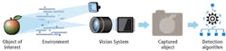
In this article, a camera-based detection system includes the following components shown in Figure 1: an object of interest in a scene; the environment that the scene is imaged through; the vision system (image sensor, lens, and light source); the captured, digitized scene which includes the object of interest; and an algorithm that identifies the objects of interest within the scene.

Figure 1: The camera-based detection system referenced in this article includes an object of interest in a scene; the environment that the scene is imaged through; the vision system (image sensor, lens, light source); the captured, digitized scene which includes the object of interest; and an algorithm that identifies the objects of interest within the scene.
Build, measure, learn – a development approach
At the beginning of development, there is often a “chicken or the egg” problem: the capability of the detection algorithm will drive the vision system requirements and the image quality produced by the vision system will drive the detection algorithm requirements. A successful design is one where the capabilities of the vision system and the detection algorithm are harmonized, thereby meeting business goals. During development, both the algorithm and vision system must be considered together. To do this well, effective iteration is required.
A flexible, iterative approach called the build-measure-learn loop, which is based on lean-startup principles, provides a framework for effective iteration through focused learning. To use this approach, ask these three questions at the beginning of each iteration:
1. What do we need to learn? This should build on previous learnings.
2. To learn this, what do we need to measure?
3. To measure this, what do we need to build? Then, only build what is required for the desired learning.
For example, we applied the build-measure-learn loop approach to the designing of a low-cost, camera-based, linear-barcode reader that can decode as many barcodes as possible across a large field of view in a single image capture. Imagine a vastly-dynamic environment where the barcode reader can move rapidly in any direction. Different-sized barcodes are in random positions throughout the environment at various angles and distances from the barcode reader.
Using the build-measure-learn loop approach, the first step was to learn the required “class” of image sensor and lens, which would set a baseline hardware cost target (Figure 2). To learn this, we measured the baseline camera’s ability to produce quality images using decoding accuracy as a metric. To measure this, we built a camera using an off-the-shelf lens and image sensor development kit. A small dataset was collected, and a first-revision algorithm was developed using off-the-shelf blocks.
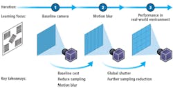
Figure 2: The build-measure-learn loop in action shows the example of designing a low-cost, camera-based, linear-barcode reader.
The first iteration learning yielded more than just the required image sensor and lens, and baseline camera cost estimate. We also learned that motion blur was the primary noise source limiting detection accuracy.
We carried these learnings into iteration two, and focused on solving the motion blur issue. To learn this, we measured the camera’s ability to produce quality images in fast-motion scenarios. Leveraging the learnings from iteration one, we devised a method to reduce motion blur using short exposure time and a global shutter image sensor. A new camera was built using off-the-shelf components and a global-shutter sensor. Another dataset was collected, the algorithm was revised, and image quality and algorithm performance assessed.
The key learnings from iteration two were that the global shutter approach worked and that increasing the algorithm capability even further would enable the use of an even lower-cost image sensor. As more iterations continued, additional learnings guided decisions to a successful design comprising a custom vision system with an off-the-shelf lens, global shutter image sensor and a highly capable algorithm. Using this build-measure-learn loop approach helped maintain focus on the next important learning and reduced non-value-add investigations. It increased the effectiveness of the iterations and resulted in a design that met business goals where the capabilities of the vision system were harmonized with the capabilities of the algorithm.
Sampling and sharpness – a starting point
Spatial resolution is arguably the most impactful image quality characteristic, so it’s a logical place to start when designing a camera-based detection system. Spatial resolution defines the size of the smallest possible feature or object that can be detected in an image and can be split into two components: sampling and sharpness.
Sampling is the pixel count over a given area, typically expressed in pixels per inch or pixels per mm. Since it’s a function of optical system magnification, it varies with object distance. Insufficient sampling reduces discriminating detail and adds aliasing artifacts. To determine a system’s sampling requirements, the physical size of distinguishing features, maximum detection distance, and required pixel count for accurate detection must be known.
To accommodate challenging situations, start with a pixel count of 4-5 pixels across the distinguishing features at the maximum detection distance where magnification is lowest. Often, to start, it’s unclear what the discriminating features are or will be, especially when applying machine learning or deep learning. To start with, it’s better to over-shoot on sampling because sampling can be more easily decreased than increased in software, allowing experiments to be done with the algorithm to determine the minimum sampling required.
Driving the sampling requirements back to the vision system parameters is easy using thin lens equations. This is especially true for an optical stack with minimal distortion. Ultimately, the sampling requirement will drive the image sensor pixel count, the image sensor pixel size, and the lens focal length. The exciting thing about thin lens equations is that these parameters can be computed and evaluated on paper before ever purchasing image sensor or lens components. Twisthink has created an Excel worksheet (Figure 3) using these thin lens equations for quick iteration, which can be downloaded at: http://bit.ly/VSD-TWI.
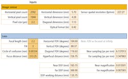
Figure 3: Twisthink has created an Excel worksheet using thin lens equations for quick iteration, which can be downloaded at: http://bit.ly/VSD-TWI.
If the optical system has about 5% distortion or more, the thin lens equations don’t accurately model the system. Driving sampling back to the vision system parameters becomes more challenging – requiring components in hand and laboratory measurements.
Sharpness is a measure of the image’s spatial frequency. Often discriminating details will have high-spatial-frequency content. When assessing vision system parameters that affect sharpness, it’s easiest to look at it from two different scenarios: static, non-moving and dynamic.
In the static case, the top three influencers on sharpness are the environment, lens and image sensor:
- Fog, dust and particulate in the environment will blur the image, so account for these in your systemdesign.
- Low-quality lenses and the focus of the lens on the image sensor will introduce blur. Other factors include temperature and manufacturing – blur varies across temperature and from lens to lens due to manufacturingvariation.
- Image sensors introduce blur with pixel cross-talk. This varies with spectral wavelength and most image sensor suppliers will provide such information uponrequest.
When there is motion, the motion speed coupled with the exposure time determines the level of blur in the image. To reduce blur, limit the maximum motion speed and/or minimize the exposure duration, which will affect many other vision-system parameters, like image brightness, lighting intensity and more.
Evaluating system performance
Once you have a system in place, a great way to evaluate system performance is with a dataset. Datasets are used to train machine learning and deep learning algorithms and they can be used for insights when designing traditional computer vision algorithms. Datasets also enable frequent and efficient evaluation of the system’s performance and provide valuable insight into whether or not a solution functions as intended.
Twisthink uses a tool called the algorithm development framework to collect data, manage and process data, and develop and evaluate efficiently. The framework has five sections that include: the vision system, dataset collection, ground truthing or labeling, algorithm development and performance evaluation as shown in Figure 4.
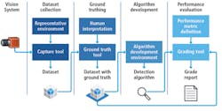
Figure 4: Twisthink uses a tool called the algorithm development framework, which allows them to collect data, manage and process data, and develop and evaluate efficiently.
For accurate system evaluation, the dataset must be collected with a representative vision system in a representative environment. Ideally, the final version of the vision system should be used to collect a dataset. If this is not possible, collect small, preliminary datasets with representative components while the vision system is being designed.
Having the answer that the algorithm should produce alongside the dataset is key to evaluation. This is known as the ground truth or label. Usually ground truthing requires human interpretation and is often an expensive step. However, a dataset with ground truth can become a proprietary asset that enables product development.
Once an algorithm is developed, the dataset and the ground truth are used to evaluate system performance. Performance evaluation requires defining a metric to measure the system performance. Using a pre-recorded dataset for evaluating system performance can accelerate development, however, confidence in the solution is driven by the content of the dataset. Consequently, it’s important that the dataset be designed to represent the application space.
Using a dataset to evaluate system performance is like black-box testing in the software world. However, sometimes lower-level “unit” testing must be performed. One way to do this is by modeling the signal path to understand noise sources and their impact on image quality. Figure 5 shows the major components of the camera-based detection system. Each component is affected by different noise sources and each noise source plays a part in the captured image quality. Different transfer functions or noise sources from each component, applied at each step, influence the original signal.

Figure 5: Modeling the signal path helps developers understand noise sources and their impact on image quality.
Modeling the signal path can give insight into non-obvious noise sources and whether or not they have an appropriate solution. It can also help identify which noise sources require further study or experimentation. Lastly, it can help understand interactions between components and be used to guide development by prioritizing low “hanging fruit.”
When you engage in the complex task of designing an embedded camera-based detection system, use the best practice of starting your algorithm development with the vision system. And remember to use an iterative development approach, start with the top image quality characteristics (sampling and sharpness) and use a dataset to evaluate the system performance.
Ryan Johnson, Lead Engineer – Computer Vision, Twisthink (Holland, MI, USA; www.twisthink.com)