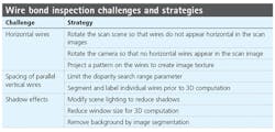
Using 3D stereo vision to inspect bonding wires

Overcoming challenges of horizontal wires, parallel vertical wire spacing, and shadow effects in wire bond inspection
Dr. Timo Eckhard
3D stereo imaging techniques are often used in bonding wire inspection, but numerous challenges exist. One example is the difficulty in using block-matching algorithms for solving the correspondence problem, since certain bonding wires may have a horizontal structure that is void of texture. For objects like this, correspondence searches can fail or perform low as the image content of the algorithm is identical for multiple blocks in a horizontal direction.
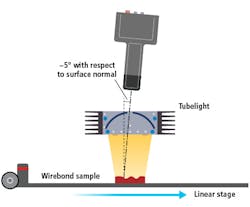
Figure 1: This schematic illustration shows how the imaging system components are positioned.
Additional challenges include parallel vertical wire spacing and shadow effects.
Fortunately, overcoming these limitations is possible and that process begins with the optimization of a 3D stereo imaging system for the inspection of bonding wires.
Since bonding wire diameter may range from a few microns to a few hundred microns, optical resolution is highly application dependent, and developers must carefully consider height resolution, height range, and field of view when selecting a suitable industrial camera for wire bond inspection applications.
Related: Multiple 3D methods ease industrial automation applications
Tube lights are generally the most suitable light source for wire bond inspection applications. Such devices provide homogenous spatial illumination with outstanding temporal and spectral stability to help keep the appearances of the images constant over time.
To ensure an optimized setup, users must consider working distance and thus install the camera and light source a proper distance from the scan surface. (Figure 1). Mounting the camera at an angle of approximately 5° with respect to the surface normal (scan line)—as opposed to mounted at 0°—enables the imaging of an object at a location where the scene illumination is stronger.
To accurately measure heights from central perspective despite the tilted position of the camera, values are multiplied with the cosine of the tilt angle (Figure 2).
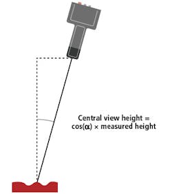
Figure 2: Correction of the camera tilt angle in height measurements can be accomplished with an equation.
Horizontal wires and the correspondence problem
Stereo imaging applications use a correlation-based block-matching algorithm for solving for correspondence. The correspondence search among left and right image of a stereo pair is performed in a horizontal direction along the sensor line.
As previously mentioned, correspondence searches can fail or perform low with bonding wire inspection, as the image content of the block-matching is identical for multiple blocks in a horizontal direction.
An illustration of this problem is shown in Figure 3, where the disparity image shows valid disparity values (homogeneous gray) for non-horizontal wires, and potentially wrong or not correlated values (inhomogeneous gray and black regions) for horizontal wires.
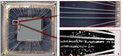
Figure 3: From the disparity image, we see valid disparity values (homogeneous gray) for non-horizontal wires, and potentially wrong or not correlated values (inhomogeneous gray and black regions) for horizontal wires.
Three potential solutions to this problem include:
- If possible, rotate the scan object in the image plane such that no wires appearhorizontally.
- If possible, rotate the camera such that the scan line is not perpendicular to the scan direction.
- Use a pattern projector to create unique image texture on thewires.
Rotating the camera with respect to the scan direction such that the wires and the sensor line are no longer parallel helps prevent identical image content across multiple horizontal blocks and avoid potentially mismatched or not correlated values.
Related: 3D vision helps robot pick small parts from large bins
When using line-scan cameras, sheared image content resulting from this rotation may cause inaccuracies when making 2D geometrical measurements. Consequently, it’s important to compensate for such image shear using geometrical calibration and subsequent image post-processing. Small angles of rotation don’t typically influence RGB image quality. However, with increasing angles, single-channel 3D computation may be required to reduce the influence of red, green, and blue pixels shifting in the sensor direction and the resulting optical low-pass filtering of the color image.
Spacing of parallel vertical wires
The height range of the objects in the scan scene typically determines the minimum required distance of parallel vertical wires for 3D calculation to work, a relationship that depends on how the correlation-based block-matching algorithm works.
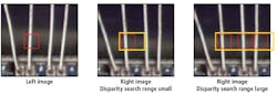
For example, Figure 4 shows left and right images of a stereo pair. The red marked region in the left camera image shows a reference block of a given window size. The block-matching algorithm searches the corresponding block in the right camera image within a predefined disparity search range, which is indicated in yellow.
Note that the rather small disparity search range in the middle image includes only one wire — the one that matches the reference block. The right image, in contrast, illustrates a case with the disparity search range covering multiple wires where block-matching might fail due to ambiguous correspondence.
Because the disparity search range determines the height range of the 3D measurement and typically depends on the minimum and maximum object height in the region of interest for the inspection task, limiting the range to ensure unique matching is not always possible. For such applications developers should consider using other approaches such as segmenting individual wires in right and left images in a stereo pair, and labeling corresponding wires, via standard 2D image processing algorithms. If the image location of the start and end of the wires or solder spots are known, the labeling task should be relatively straightforward.
Related: 3D imaging enables high-speed bore inspection
After this it’s possible to create artificial image pairs that contain only wires where unique matching is possible within the disparity search range and merge the corresponding disparity images into a single height map. The trade off with this approach is increased computational demand, which grows with the number of image pairs with individual wires that require processing. One way to speed up the system is to use distributed computing with multiple instances in parallel and at least one GPU per instance.
Computing 3D coordinates from corresponding image points of a stereo image pair is also possible through Chromasens 3D-API’s rawImageCoordinatesTo3D function. Based on that, solving the vertical wire problem is possible by using image processing to extract corresponding points on the wires of the right and left stereo images. Merging the resulting discrete 3D coordinates to a global representation of the wires in a 3D image is also possible. By using this method, an application-specific image-processing-based wire detection approach replaces the image-correlation-based block matching approach.
Shadow effects
In a scan scene, directional lighting often results in shadows cast by the wires onto the background. Tube lights reduce this effect. However, when inspecting certain background materials and wires, residual shadow effects may remain (Figure 5).
Such shadows create issues when image content of a correlation window of the left and right images contains distinct shadows in corresponding regions. In such instances, the blocks don’t match and the correlation value is low.
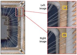
Figure 5: Shadow effect in a left and right image of a stereo pair is illustrated.
The perspective difference between left and right cameras makes shadows appear in distinct locations of the stereo images. Improving the scene lighting—which is not always possible and might require complex custom-made light sources—is one method to overcome the problem.
Reducing the correlation window block size is another approach. However, it’s necessary to select the minimum required size while ensuring that enough unique texture features remain for 3D computation in a corresponding window. Removing shadows from the stereo image pair through image-processing techniques such as segmenting the wires from the background that contains the shadow effect is also possible. After removing background regions by setting to a zero value, Chromasens’ 3D API—through configuration—can ignore these regions in the computation.
While the challenges of horizontal wires, parallel vertical wire spacing, and shadow effects create difficulties for the successful implementation of 3D stereo vision systems for wire bond inspection applications, methods exist to overcome these obstacles.