Vision helps robots inspect truck beds
By Andrew Wilson,Editor
DaimlerChrysler has developed an integrated robot-vision system that inspects racks of truck-bed parts for proper type and position prior to assembly.Labor-intensive applications such as those in automobile manufacture are ideal candidates for automated robotic assembly systems. Eliminating the tedious and repetitive manual tasks performed by operators by installing automated machine-vision systems can increase productivity and abolish operator errors.
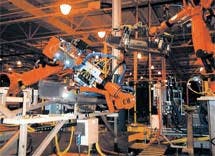
In automotive assembly, large, heavy objects must often be automatically manipulated, inspected, and moved to the next manufacturing process. DaimlerChrysler (Twinsburg, OH) faced such tasks in automating the production of its new full-sized Dodge pickup trucks. To automate the truck-bed inspection and assembly of these vehicles, DaimlerChrysler enlisted Shafi Inc. (Brighton, MI), Cognex Corp. (Natick, MA), and Nachi Robotic Systems (Novi, MI) to develop an integrated robot and vision system that could inspect the racks of truck-bed parts, unload different sized parts from a rack of 18 parts, and then place them with camera vision guidance onto a fixture for the next stage of part assembly. With the flexibility, reliability, and reduced cost of off-the-shelf robots, vision systems, and software, the changing geometries of truck-bed parts will not require DaimlerChrysler to retool part racks and trays for new truck models.
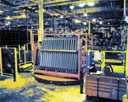
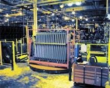
Parts and racksTruck-bed parts are stamped in a plant of the Twinsburg facility and transported on racks via forklifts to the assembly side of the plant. Because these parts differ in size, they are mounted in two different racks, which contain eighteen parts per rack. These 3 x 2 x 1-m racks, each weighing 1700 lb, are manually delivered to the production line by an operator-driven forklift The driver uses the forklift to place the racks on a large turntable that can be rotated 180° to the robot unloading position (see Fig. 1). However, before rotating the racks to the robot unloading position, a series of inspection checks is performed to qualify the racks as being suitable for unloading. If any inspection check fails, the inspection system generates an error message that is displayed to the operator and no unloading occurs.Three checks are performed on both the rack frame and its securing bar prior to unloading. First, the rack's securing bar must allow the robot access to the parts. Next, the rack frame is checked for squareness and height. While three bars at the top of the frame determine if the rack is square, the height of the rack determines whether 6.5- or 8-ft racks are present. Last, all 18 parts per rack are verified as being well spaced, right- or lefthand parts, and proper space is available for the robot to pick and place the parts correctly.
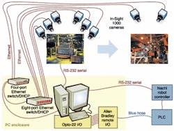
To perform these inspections, six Cognex In-Sight 1000 vision sensors are mounted above the robot inspection station (see Fig. 2). Interfaced to an industrial PC running Windows 2000, Cognex In-Sight PC software, and Shafi Reliabot PC user-interface software direct the operations of the six smart cameras in inspecting the front and top surfaces of the rack. The cameras use a 6-mm lens that allows them to be placed 8 to 9 ft away from the racks being inspected. This provides ±0.15-in. resolution, which is well within the system requirements.
"Before any inspection can be accomplished, the vision system is calibrated using a 'golden' or 'master' rack of parts," says Adil Shafi, president of Shafi Inc. "To accomplish this, the PC running Reliabot PC software is connected to the In-Sight vision sensors via an Ethernet. It guides the operator through a simple calibration procedure," he adds. Once calibrated, the incoming racks can then be automatically inspected. "In the future, we plan to use statistical data on the racks to reach an optimum rack profile for setting pass/fail tolerances for pre-unload inspection checks," says Shafi.
To perform the first three checks, Shafi uses the toolbox of 200+ vision tools and commands that is supplied with the In-Sight 1000 sensors. Each sensor's camera uses blob-analysis and edge-detection tools to determine the presence of the securing bar, check that all parts are present, and verify that all the parts are straight. These measurements are recorded in a spreadsheet format by the cameras and delivered to the host PC over the Ethernet interface. Here, Shafi's Reliabot PC software analyses the data and reports each inspection as pass or fail to the operator. If all the inspections pass, the vision system can proceed to the robotic pick-and-placement stage.
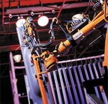
Pick and placeAfter both racks and their parts have been checked, the parts from each rack must be robotically handled to the next fixturing stage. To accomplish this, the six In-Sight 1000 sensors calculate the trinocular geometry among three cameras facing directly downward and three cameras angled down toward the horizontal side of the rack.Once calculated, the three-dimensional (3-D) coordinates of each part in the rack are used to control the movements of an SF166 robot from Nachi Robotic Systems. Under control of the Reliabot software, these parameters are passed to the SF166 robot over an RS-232 interface. The robot is then directed to pick the first part from the rack (see Fig. 3).
"In operation, the Nachi robot picks a 6.5- or 8-ft part from the rack using suction-cup grippers," says Shafi. "However, when the parts are pulled out from the rack, slippage can occur due to a combination of parts not sitting perfectly in the rack and oily film on the stamped parts." This problem can create a grip position variance of up to 50 mm.
After a successful pickup, the parts are mounted horizontally onto the next assembly fixture that contains two locking pins. Because the positional repeatability needed is ±3 mm and the entire part is 6.5 or 8.0 ft wide, a single camera is unable to image the entire part for proper pickup. Worse yet, much of the part's area is obstructed by the robot gripper's components, which occlude the middle view of the part.
Consequently, two additional In-Sight 1000 sensors are mounted to the plant's ceiling. The two sensors' cameras are used to locate the part and determine the corrective linear and angular offsets that the robot needs to place the part on the fixture. To do so, a pattern of small holes at the ends of the part are imaged by the cameras with a small field of view (FOV), a large object-to-lens distance (from the plant ceiling), and the Cognex PatFind pattern-matching tool. The ceiling mounting of the cameras eliminates the need to maintain focus, aperture settings, and compensate for vibrations from objects on the factory floor. The two cameras' FOV are then linked to create an overall offset for the robot in robot coordinates (see Fig. 4).
Connected through an Ethernet switch to the system's host PC, each of the two ceiling cameras focuses on one end of the truck-bed part. Because the most visible features in the FOV of each camera are the part's outline and three holes, these features are used by each vision sensor to determine the location and angle of the part. With a FOV of each camera equal to 40 x 30 in. and a camera resolution of 640 x 480 pixels, location accuracy is ±0.159 mm, which is well within the required ±3 mm needed for part placement.
"In theory, the FOV accuracy remains ±0.159, even with only one camera," says Kevin North, manager of software development at Shafi. "But since the part is gripped by the robot at its center, any small errors in the part's angle are magnified at the opposite ends of the part." However, with two cameras, an angle can be precisely calculated using two measurement points, one at each end of the part.
Ideally, the part should be taken to a special, controlled vision image-acquisition area prior to placement. However, plant cycle times do not permit such staging, and the only location for vision inspection is prior to fixture placement. Like the cameras used in part and rack inspection, the two ceiling cameras are each equipped with 12-mm lenses and are mounted approximately 9 ft above the part. Although the robot end-of-arm tooling obstructs the view of the part, the measurement holes on the extreme ends of the part are visible, and the end-of-arm robot tooling is ignored by the vision system and is not included for pattern matching of the images.
During vision-system operation, the two ceiling In-Sight vision processors use the Cognex PatFind tool to find a pattern and then find the center of one of the part's measurement holes. Using the coordinates of the holes determined by the two ceiling sensors, an x offset, a y offset, and a rotational angle are calculated for the tool center point of the robot. This information, which is computed using the Reliabot software, guides the robot to place the part over the fixture assembly so that the part can be moved to the next stage of the assembly process. The information is passed to the robot over an RS-232 serial link.
"To provide even lighting from the ceiling and overcome other ambient lighting on the factory floor, two 400-W, metal-halide lights illuminate each inspection stage," says Shafi. "And to see the part outline and holes clearly in the captured images, both the floor and pick locations are darkened."
Display functionsThe robotic-vision-handling system has been in operation at the DaimlerChrysler plant for several months. Upon delivery of a new rack, the forklift driver is presented with a 15-character display from the system's host computer that textually explains the status of the rack. This display is easily seen because it is presented in the driver's line of sight. After the rack of parts is delivered from the stamping side of the plant, it is placed onto the turntable. The production floor operator then pulls down a retaining bar and activates the system checks.The display indicates whether the correct rack is in place and whether the parts are properly positioned within the rack. At this point in the inspection process, both the forklift driver and the floor operator can correct any problems and repeat the check. The driver then collects another rack of parts while the turntable is turned 180° toward the robot side for unloading and placement onto the fixture pins for subsequent handling by downstream robots.
Company InformationAllen BradleyMilwaukee, WI 53204Web: www.ab.comCognex Corp.
Natick, MA 01760
Web: www.cognex.com
DaimlerChrysler
Twinsburg, OH 44087
Web: www.daimlerchrysler.com
Nachi Robotic Systems Inc.
Novi, MI 48375
Web: www.nachirobotics.com
Shafi Inc.
Brighton, MI 48116
Web: www.shafiinc.com
