Wavefront-coded imaging enhances vision
Signal processing and custom lenses extract information and render high-quality images.
By Ram Narayanswamy, Vlad Chumachenko, and Greg Johnson
As imaging systems become more ubiquitous, more is expected of them in terms of performance, cost, size, and ease of use. For example, miniature cameras are expected to deliver high-resolution, wide-angle images without any distortion or color artifacts. Cameras in general have to maintain good focus over a large distance (implies small aperture) while maintaining high resolution (large aperture). Lenses have to be compact and use fewer optical elements without sacrificing performance. Such requirements are often contradictory and are impossible to meet with conventional design approaches. The next generation of imaging systems will need innovative approaches.
Traditionally, digital imaging systems are viewed as having two functional units--the lens that forms the image on the focal plane and the electronics that digitize the optical image. The lens, the electronics, and any postprocessing are designed independently of each other with little regard for the overall imaging system performance. Imaging performance can be significantly improved by designing all three components as part of a single cohesive system.
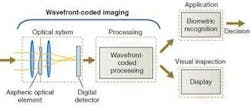
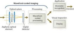
Wavefront-coded imaging is a new technique in imaging systems that uses signal processing as an integral part of image capture. In additional, wavefront-coded imaging uses custom lenses that are optimized specifically for each application. This combination of an application-specific lens and signal processing can deliver performance that is impossible with traditional imaging systems.
Wavefront-coded imaging can be explained by drawing an analogy to communication systems, where signals are encoded for transmission across a channel and decoded upon reception to extract the relevant information. The wavefront-coded optical element codes the optical wavefront from the scene in such a manner that the relevant information about the scene is retained at the focal plane. The sensor in a wavefront-coded system is a typical CCD or CMOS sensor, and it digitizes the coded image at the focal plane. The signal processing decodes the coded image and delivers an image with minimum artifacts and defocus error.
The wavefront-coded image prior to processing (“coded image”) resembles a blurred image of the scene except that the blur is independent of object distance (see Fig. 1). Objects in the foreground and background appear equally blurred, which is contrary to a traditional imaging system.
INCREASED DEPTH OF FIELD
Typically imaging systems are focused at a nominal object distance from the lens. Objects that are far removed from this nominal distance are blurred and have defocus error. Conversely, objects in and around the nominal distance are imaged in sharp focus. Depth of field (DOF) is the distance between the nearest and furthest points where objects appear in acceptably sharp focus.
A large DOF is desirable because it reduces the need for actively focusing the lens. The alternative to a large DOF is autofocusing, where the lens is mechanically focused for each frame. Autofocusing adds considerable mechanical complexity and wear-and-tear issues that lead to higher cost of ownership. On the production floor, where throughput is critical, the time taken to refocus the lens translates to reduced system throughput. In other scenarios, such as web-based-production, a shallow DOF imposes tight tolerances on the material handling equipment. Such tolerances lead to higher capital costs and longer down time to keep the system tuned within the specification.
The DOF of an imaging system varies with the entrance pupil diameter, the focal length, and the object distance. In the case of a simple lens, the entrance pupil is the same as the lens aperture. With the focal length and object distance held constant, reducing the lens aperture increases the DOF. However, reducing the aperture also leads to lower light captured from the scene and lower resolution.
In addition to the DOF, the focal length and the aperture also determine the light gathering capacity of the lens, which is usually denoted by thef-number (f/#). The f/# is the focal length of the lens divided by its entrance pupil diameter. Lenses with a large entrance pupil compared to their focal length (small f /#) capture more light from the scene compared to lenses with a smaller entrance pupil (large f /#). Each increase in the f/#, which goes as f /1, f /1.4, f/2, f /2.8, f /4, f /5.6, f /8 . . . , reduces the light-gathering capacity by 50%. Thus, doubling the DOF by going up two f-stops implies reducing the light captured to 25% of the original amount of light.
Reduction in the light-gathering capacity of the lens has other implications. The acquired images may suffer from lower contrast and lower signal-to-noise ratio (S/N). The illumination system may need to double its power with each increase inf/#. The camera may be required to operate at a longer exposure time to capture more light. Reduced contrast can lead to poor detection. Increasing the illumination leads to power, heat, and source lifetime issues. Longer exposure time can lead to motion blur that offset the gains from the increased DOF.
In addition to the light-capture capacity, the lens aperture also has implications for resolution. The maximum spatial frequency of the lens is directly related to the aperture size. Reducing the aperture by half halves the optical resolution. This trade-off is often not considered by system designers since imaging systems tend to be undersampled and the cut-off spatial frequency is determined by the sensor’s pixel pitch, rather than the lens aperture. However, atf/16 or higher, the diffraction limit could be the limiting factor and have adverse effects on the application.
Wavefront-coded imaging can deliver systems that operate with large apertures (lowf/#) but offer the DOF of a reduced aperture system. Typically wavefront-coded systems can increase the DOF by a factor of three to five times that of a traditional system (non-wavefront-coded) while maintaining the equivalent f/#. For example, the lens can be operated at f/2 but deliver the DOF of a lens operated at f/8.
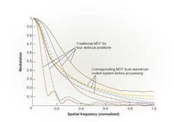
Wavefront-coded imaging is best explained in the frequency domain using the modulation transfer function (MTF), which is the Fourier transform of the system point-spread function (or impulse response). The MTF plots contrast as a function of spatial frequency. For an object at the best focus position the MTF curve looks like a triangle, with the 0th spatial frequency having the highest contrast and the contrast reducing with increasing spatial frequencies. As the object moves away from the best focus position, the contrast at the high spatial frequencies drops rapidly (see Fig. 2). Once the contrast drops below the noise floor or below some detection threshold, all information in those frequencies is lost. This loss of information at the higher spatial frequencies leads to objects appearing blurred.
The rate at which the contrast drops depends on the size of the aperture. A system with a larger aperture loses contrast more rapidly than a comparable system with a smaller aperture. Thus, a higherf/# system appears to maintain focus over a large range of object distance and have a higher DOF.
Wavefront-coded systems operate by coding the wavefront such that the MTF of the system does not vary significantly with object distance. As the objects move away from best-focus position, the contrast at the higher spatial frequency does not drop below the detectable threshold or the noise floor. Thus, the information at these spatial frequencies is still retained. With the contrast maintained above the noise floor, the processing boosts the spatial frequency to the desired levels to form crisp high-contrast images. The processing is typically linear and achieved by convolving the image with a filter.
A traditional image maintains good focus. The tapes in the foreground and background of Figure 3 are blurred such that the letters on them are rendered illegible. The corresponding wavefront-coded system maintains the entire field of view (FOV) in sharp focus and the letters are legible through the entire imaging volume. The wavefront-coded system is also able to correct some of the color artifacts such as the color aliasing seen in the letters “Hewlett-Packard” and the numeral “2” near the best-focus position.
Security systems monitoring outdoor scenes typically use a short-focal-length lens since it provides a wide FOV. The focusing characteristics of such a system are measured by the distance to the nearest object in the scene that is sharp when the lens is focused at infinity. The shorter this distance, the greater the DOF becomes.
Figure 4 illustrates the use of wavefront-coded imaging to recognize signs at a distance that would be the case in a security application. The traditional and wavefront-coded systems are both focused at infinity. The license plate held in the foreground is 1 m from the lens. The wavefront-coded system is able to resolve numeral “05” quite clearly, while it is rendered illegible in the traditional system.
Wavefront-Coded imaging
From a broad systems perspective, wavefront-coded imaging allows a designer to trade excess signal-to-noise ratio for increased depth of field. When considering wavefront-coded imaging, the designer should understand the maximum resolution and minimum contrast required by the application. The contrast over and above the minimum required by the application can be used to increase the depth of field of the imaging system.
Wavefront-coded imaging has an associated computation cost. The “decoding” operation involves convolving the “coded” image with a linear filter. The number of
coefficients in the filters can range from 5 × 5 to 100 × 100, depending on the application. The tape-inspection application shown in Figure 3 and the security application shown in Figure 4 use filters that have 15 × 15 coefficients. The processing can be performed on a wide range of platforms including PCs, FPGAs, or DSPs. The processing power required is well within the capacity of current computation engines. Real-time wavefront-coded systems operating at 60 frames/s or higher have been demonstrated by CDM Optics and third-party vendors.
RAM NARAYANSWAMY and GREG JOHNSON are directors andVLAD CHUMACHENKOis a systems engineer at CDM Optics, Boulder, CO, USA;
www.cdm-optics.com.


