Applying algorithms for machine vision
Andrew Wilson, Editor
When tasked with developing a machine vision system, developers can chose from a number of different software options. For those developers wising to embed image processing algorithms into their code, callable libraries can be used to perform well-understood imaging functions such as optical character recognition, image measurement and pattern matching.
At a higher, more abstract level, software vendors such as Matrox (Dorval, Quebec, Canada; www.matrox.com), MVTec (Munich, Germany; www.mvtec.com), National Instruments (Austin, TX; www.ni.com), Tordivel (Oslo, Norway; www.scorionvision.com) and Teledyne DALSA (Waterloo, Ontario, Canada; www.teledynedalsa.com), now offer development tools that allow a number of different functions to be represented graphically, alleviating the need for the developer to understand the underlying code. Taking this one stage further, graphical vision "frameworks" from Companies such as ControlVision (Auckland, New Zealand; www.controlvision.co.nz) are now emerging that abstract the underlying code of a number of software vendor's packages as graphical representations.
In this manner, developers can graphically "drag a drop" different functions from multiple software vendors and combine them to perform a single machine vision task. While such software is useful to rapidly develop machine vision systems, developers must often pay run-time license fees when such software is deployed. In many cases, this may prove to be just the fraction of the cost of the complete system.
In other cases, the developer may wish to develop an application writing the code in a high-level language and/or using open source software such as OpenCV. Whichever approach is taken, it is necessary to understand some of the underlying concepts behind image processing algorithms.
As Ganesh Devaraj CEO of Soliton Technologies (Bangalore, India; www.solitontechcom) points out, in many different image processing applications, only a few vision algorithms may be required (see "Applying Algorithms," Vision Systems Design, November 2008, http://bit.ly/101XIMZ). These include thresholding, blob analysis and image detection.
Three classes
Such algorithms can be classified into three different classes: point, local and global. Point processing algorithms take an input image and generate an output image where the output value of a specific pixel is only dependent on the input value at that same co-ordinate. Such point processing algorithms can be used in a number of different ways to enhance images. One of the most useful types of point processing algorithms is image subtraction in which one image is subtracted from another.
Although simple, the concept is very powerful. Such algorithms are commonly used in fluoroscopy techniques such as digital subtraction angiography where it is necessary to highlight blood vessels. In this process, an image of the tissue is first imaged before a radiological contrast agent is injected into the patient. After taking a second image, the images are subtracted, resulting in a final image where the blood vessels become more clearly visible.
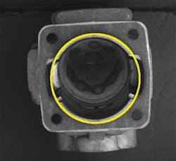
Such simple algorithms are also useful in machine vision applications, where, for example, an object may be improperly illuminated. In such applications, it is often necessary to highlight specific features within an image. If a backlight is used to image an automotive part, for example, and the task is to measure the diameter of the part, then simply thresholding the image may suffice.
To perform this task, a histogram of the image is first computed that shows the number of pixels in an image at different pixel values. An intensity threshold is then set and each pixel in the image compared with this threshold. If the pixel value is higher than the threshold, the pixel value is set to white. If the pixel value is lower than the threshold the pixel value is set to black. This global thresholding results in a segmented binary image of the part that can be more easily measured.
Where lighting may be non-uniform, however, such a simple thresholding technique alone may not suffice. In some cases, it is necessary to eliminate any background non-uniformity. To accomplish this, a light field of the scene under illumination is first imaged. This can be performed by imaging the scene with a uniform white surface. A captured image of this uniform surface will then show the non-uniform light distribution. If this image is then subtracted from an image of an object under the same illumination conditions, any variation in background illumination will be reduced. After this is performed, the image can then be thresholded to more accurately segment the captured object.
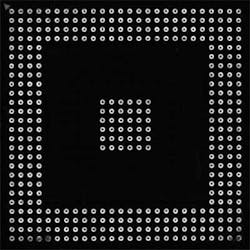
Generating an image histogram of an image is also useful when contrast enhancement needs to be performed. In a method known as histogram equalization, pixel values in the histogram of the original image are remapped to another histogram distribution that features a wider and more uniform distribution of pixel values (Figure 1). By spreading these intensity values, the contrast of the image is enhanced. In many machine vision applications, enhancing the contrast of an image is used as a pre-processing step to local image processing algorithms.

Local operators
Rather than generate an output image where the output value of a specific pixel is only dependent on the input value at that same co-ordinate, local image processing algorithms generate an output image at a specific pixel based on the input values in the neighborhood of the input pixel. This technique is particularly useful to perform image sharpening, smoothing or finding edges in an image.
To perform this task, a convolution kernel is first chosen to produce the desired effect. To reduce the amount of noise in an image, for example, a mean filter can be used. This filter replaces each pixel value in the image with an average or mean value of both its neighbors and itself. A typical 3 x 3 convolution kernel to perform this task may then consist of a 3 x 3 array with values of 1/9th. When this kernel is convolved across the image, the result is an image with any high frequency components such as noise reduced. In this respect the algorithm acts as a low-pass frequency filter.
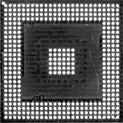
Although mean filters are useful, a more robust method of reducing noise in an image is the median filter. Here, instead of replacing each pixel value in the image with an average of both its neighbors and itself, the pixel is replaced with the median value. Because this median value represents one of the pixels in the image, the median filter retains the edge information in the image while at the same time removing noise (Figure 2).

While such filters are useful for noise removal, it is often necessary to highlight the edges within an image so that some form of measurement can be later made. Here again, convolution kernels can be used to perform this task. One of the most popular of these is the Sobel filter. To highlight edges within an image, it is necessary to determine the transition points from light to dark in the image. This is accomplished by calculating the gradient of the image intensity at each point by convolving two kernels across the image to highlight the gradient in both horizontal and vertical directions. Other commonly used filters that use this same principle include the Prewitt and Roberts Cross and Laplacian operators.
While such filters may be effective in highlighting the edges of an image, in many cases, there will be missing pixels in these edges, making automated measurement difficult. To ensure lines curves and circles can be more accurately located, the Hough transform can be used after an edge detection algorithm is performed.
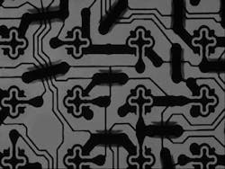
Knowing that the (x, y) co-ordinates of any pixel along a line can be represented in polar co-ordinates as ρ =xCos θ + ySin θ, each value of x and y in the image will generate a sinusoidal curve in polar co-ordinate space. Performing this for bright pixels that represent edges in the image will then result in a number of different overlapping sinusoidal curves. If the curves of two different points intersect in the ρθ plane, then both points are classified as belonging to the same line. This line then can be graphically overlayed on the image and used to compute image features. Similarly, the Hough transform can be used to determine other geometric features such as circles and ellipses by substituting the relevant Cartesian to polar co-ordinate equations (Figure 3).
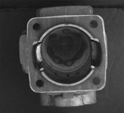
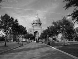
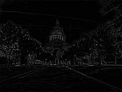
While finding such features in images is extremely useful, it is often necessary to locate regions (or "blobs") that are similar within an image. Perhaps the most common transform to perform this task is the Laplacian of Gaussian – an algorithm that can be implemented using convolution. After the image is first blurred using a Gaussian convolution kernel to remove noise, another convolution kernel is applied that approximates the second spatial derivative or intensity change of pixel values across the image. Applying both these kernels then results in an image where the edges of the object have been highlighted (Figure 4). This information can then be used, for example to find the area of the object or its center of gravity.
Global transformations
While point and local transforms form the basis of many commercially available image processing libraries, the third class of image operators – global transforms – produce an output pixel value at every (x, y) co-ordinate based on all the values in the input image. One of the most commonly used global transforms in image processing is the Fourier transform. Applying the transform to an image results in an image where each point represents a particular frequency of the original image (Figure 5).
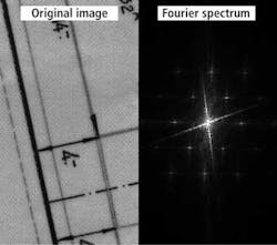
Because image convolution in the spatial domain (such as Sobel filtering) is equivalent to multiplication in the Fourier of frequency domain, using the Fourier transform can prove useful in applications where large, computationally intensive kernels would otherwise need to be employed. Perhaps the most important application of this transform, however has been in image compression where a variations of the algorithm - the discrete cosine transform (DCT) – is used in JPEG, MPEG and H.261 standards.
Company Info
ControlVision
Auckland, New Zealand
www.controlvision.co.nz
Matrox
Dorval, Quebec, Canada
www.matrox.com
MVTec
Munich, Germany
www.mvtec.com
National Instruments
Austin, TX;
www.ni.com
Soliton Technologies
Bangalore, India
www.solitontechcom
Tordivel
Oslo, Norway
www.scorionvision.com
Teledyne DALSA
Waterloo, Ontario, Canada www.teledynedalsa.com
For more information, please visit the machine-vision software section of the Vision Systems Design Buyer's Guide (http://bit.ly/IJq0dP).
Vision Systems Articles Archives