Understanding other edge- and line-based segmentation techniques
Understanding other edge- and line-based segmentation techniques
ROBERT BELKNAP
In March, this column introduced a variety of edge-detection techniques (see Vision Systems Design, March 1999, p. 27). This month, Software Vision describes effects that arise when using mask-based edge operators, line-fitting algorithms, and edgel-linking techniques.
Image edges and noises consist of high-frequency information. That is, they are events that change rapidly on a pixel-by-pixel basis. Therefore, edge detectors are noisy operators, as they tend to enhance noise at the expense of the edge under detection.
One technique used to reduce noise is by averaging or blurring. However, this technique blurs edges as well. So, a constant trade-off must be made in the selection of the kernel size for a mask-based edge operator. However, another important factor must be considered. Kernel size plays an important role in the edge operator`s ability to pick out the frequency of edge detail from an image.
The term frequency means the edge thickness or spacing. In general, small kernels are better at detecting smaller edges. On the other hand, large kernels perform low-pass filtering and will therefore filter out the smaller edges, so the edge operator will not have any significant response when encountering a small-edge event. In some applications where edge directions are known to exist in only one direction, the edge-operator kernel sizes could be made larger, parallel to the edge direction, but kept smaller, parallel to the edge. In this case, the compass mask approach proves useful (see Vision Systems Design, March 1999, p. 27).
Line fitting
Another property of edge operators is that they operate as a function of the edge strength or magnitude. Therefore, in areas of an image with low edge contrast, such as a shadowed area, edge information will be lost. An edge-extraction approach based on gradient direction can be used to overcome this problem:
Create an edge image. This can be computed by one of the many masked-based operations previously discussed. The edge image consists of two values for every pixel--a gradient magnitude and direction. Each element corresponding to a pixel in the original image is called an edge element, or edgel for short.
Divide the gradient space arbitrarily into a number of orientation bins, called buckets. Each group of adjacent pixels falling into the same bucket is labeled as a distinct line-support region. Typically, small edge-support regions are discarded at this stage to eliminate small line fragments.
Fit line segments to the support regions with a least-mean-squares error (similar to a root-mean-square error, but without the final square-root computation). At this stage, the edgel magnitudes in the support regions can be used to weigh the line fits, or not.
The result is a set of line segments that are an averaged fit to the edges oriented in similar directions (see Fig. 1). Because this method only fits straight lines, edges of objects might be broken if they curve or turn. In addition, edges that creep across bucket divisions will be broken into separate line segments. This condition can be avoided by using overlapping bin partitioning, and then selecting the longest or best-line fit from each support region. Alternatively, the gradient-line-fit process can be followed by a grouping process, which links lines that have endpoints near one another.
Edgel linking
A similar approach, called edgel linking, groups edgels into linear links called chains. The grouping process is iterative. Resulting chains are extended at their ends by considering the neighbors of the endpoints and picking the best candidate if one exists. This process begins with single seed edgels chosen by their large magnitude.
Edgels are defined by their location, direction, and magnitude. Before the chaining process can begin, a neighborhood of adjacent edgels must be established for each edgel. During the chaining process, each neighbor in an edgel`s neighborhood is considered as a possible link partner. Various geometric criteria are used when picking the best-link candidate: turn angle link-to-link angle (alpha); link length edgel-to-edgel distance (length of L2); edgel-to-link angles are those between the edgels and the normal to the link (beta1 - p/2, beta2 - p/2); edgel-to-edgel angle is called gamma (see Fig. 2).
These criteria are used in two ways. First, three of the four angles must satisfy hard limits for the link to be considered: the turn angle must be less than (p/4 (a); the link length must be less than maxLinkLength (b); and the edgel-to-link angles must be less than maxEdgelToLinkAngle (c). Second, all eligible candidates for chain continuation are scored by a weighted sum of the values in (a), (b), and (c). Note that two values are included under (c). The relative weightings can be controlled with functional parameter weighting (for example, link-length-weight, edgel-to-link-angle-weight, and edgel-to-edgel-angle-weight).
Further constraints can be imposed on the chain-growing algorithm as follows:
Chains are grown from edgels with some maximum magnitude (called seeds).
Only edgels with a magnitude above some minimal seed magnitude are grouped.
Chains can be extended only with edgels that are neighbors of the end edgel.
Chains must have a minimum number of points, minimum member edgels to be included in the output image.
A given edgel can be placed into only one chain. This includes chains that are not accepted be cause they are less than some minimum number of edgels in length.
If the best continuation edgel at one end of a chain is already in cluded in a chain, then growth at that end will stop.
Some problems arise in chain linking, such as chains being broken when one edge crosses another, noise disrupting the gradient direction about an edge enough to throw off the linking process, or shadows and occlusions causing chain dropouts. These can be somewhat compensated by performing a subsequent process of chain linking, whereby the chains are merged in much the same manner as the individual edgels (see Fig. 3).
Edgel and chain fitting
Edgels and chains might themselves be used to support the fitting of edge objects such as lines, conic splines, ellipses, circles, and other higher-order shapes (see Fig. 4). For instance, a line segment can be fitted to chains. If the-line-fit error is too large, then higher-order equations/structures can be fitted. This process can be implemented as a bottom-up process similar to the grouping of edgels into chains; that is, chains are grouped in other shapes based on certain parameters, rules, or equations.
Or, the process can be goal-driven or top-down, whereby the existence of a certain shape is attempted to be supported by assuming a shape and looking for edgels or chains that make up part of the object. The former process is similar to perturbing the data and seeing what they turn into; the latter process is similar to taking a jigsaw piece and attempting to see where it fits into a puzzle.
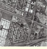
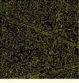
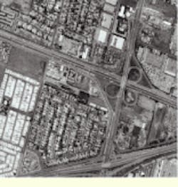
FIGURE 1. Edge-extraction techniques based on gradient direction, not magnitude, can extract straight-line segments even in situations where there is low contrast or noise.
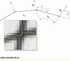
FIGURE 2. Edgel linking is a process whereby individual edge elements are grouped into linear groups called chains. Various geometric criteria are used when picking the best-link candidate.
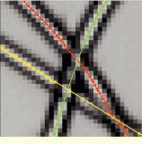
FIGURE 3. Some problems arise in chain linking, such as chains being broken when one edge crosses another. These can be somewhat compensated for by performing a subsequent process of chain linking, whereby the chains are merged in much the same manner as the individual edgels
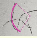
FIGURE 4. Edgels and chains can support the fitting of edge objects such as lines, conic splines, ellipses, circles, and other higher-order shapes
ROBERT BELKNAP is director of software development, Imaging Products Division, Amerinex Applied Imaging Inc., Northampton, MA; e-mail: [email protected].