Ten basic steps to successful machine-vision-system design
Ten basic steps to successful machine-vision-system design
By John Hanks and Charles Schroeder
For machine-vision and imaging-system developers, a design approach of ten practical guidelines establishes a strong architectural method for satisfying application requirements. Vision applications are challenging because each application is often unique. Apply these design steps as general rules for developing a custom machine-vision application.
Step 1. Determine inspection goals
Several studies indicate that humans are only 80% accurate in performing inspection applications. The human mind tends to wander over time while performing tedious rote inspection tasks. These studies also demonstrate that automated machine-vision inspection systems prove to be more accurate, reliable, and tireless for executing these same applications.
In setting up an automated machine-vision system, the first task is to determine the cost budget and the application benefits. Obviously, the cost of the vision system must pay for itself over the short term by improving the manufacturing process and product yield or reducing the overhead, such as support cost, returns, and so forth.
For example, in a practical web-inspection application, a manufacturer of building material estimated that 15% to 20% of its product was scrapped because of process flaws and defects. In one plant, it manufactured more than 100 million lb of material a year. The manufacturer estimated that if a machine-vision system could reduce its scrap by 50% and material cost by $0.34/lb then the resulting savings would exceed $1.7 million. It operates more than 50 plants. Because of the huge potential savings, this manufacturer quickly adopted machine vision as a core manufacturing technology.
Moreover, the cost budget also helps to answer the build-or-buy question. For the described web-inspection application, the concept of percent inspection was key. This application mandated the inspection of every 12 in. of material; therefore, 100% inspection of the material was not necessary. If 100% inspection were required, the overall system cost and complexity would have been much higher and would possibly deter the company from using a machine-vision system.
Another inspection goal concerns system variations. Again, in the described web-inspection application, system variations were important because the inspection had to take place in a harsh manufacturing environment; therefore, a ruggedized personal computer (PC) and an enclosed inspection area were required.
Another inspection goal centers on the human operator profile. Operators of the described web-inspection system were expected to be unskilled in vision technology. Consequently, this system had to be easy to configure, present a simple user interface, and require minimum calibration and maintenance.
Step 2. Estimate the inspection time
If the product-inspection time differs by a factor of ten from the overall system inspection time, then an alternative technology should be considered. In some applications, the inspection requirements are such that the machine-vision system cannot slow down the production process. Calculating the overall system inspection time should include material handling, image acquisition, and data processing.
When determining the processing time, take into consideration the type of processing needed. If the application involves gauging, then, typically, a method called edge-detection is used. This technique processes only the pixels along a line profile for alignment and orientation of the part under inspection. The line profiles and edge-detection procedures are then used to "gauge" a critical measurement. If the inspection time cannot be adequately minimized, then consult with frame-grabber, vision-software, or systems-integration companies for helpful advice.
Some techniques that can improve inspection-time performance include
-Digital cameras--provide faster image-acquisition rates (up to thousands of frames per second) than analog cameras (30 frames/s).
-MMX-enabled vision software--can increase system processing for some functions by as much as 400%.
-Image-acquisition hardware--can support such image-processing techniques as on-board partial image scanning, programmable region of interest, and on-board pixel decimation. This design strategy aims to reduce the number of processing pixels to decrease the time needed to process the image.
Use the latest personal computer available, as PCs continue to incorporate faster processors.
Step 3. Identify features or defects
Before purchasing machine-vision hardware, clearly specify the definition of a defect for the inspected part and what system aspect cannot be automated. System questions that must be answered include What constitutes a good part?, What are the most common defects of the part? , and What visible features distinguish a bad part from a good part?
Statistical techniques, such as ranking the defects from highest to lowest probability, can be used to help evaluate all the defects. If the defects cannot be classified, then the inspection process will generally be difficult to automate. At this step, it is often preferrable to get a systems integrator or a vision vendor involved. Many vision vendors will evaluate an application solution, mainly by using their hardware and software, however.
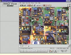
Creating an image database of defects and acceptable components is important in developing a vision strategy. For this step, it is often useful to acquire images using an inexpensive camera, frame grabber, and lighting to evaluate whether the application can be easily solved. The assumption is that if a prototype vision system works somewhat adequately, then the application could be readily solved with optimal lighting, optics, and hardware (see Fig. 1).
In addition, having a database means that the lighting companies and vision-software vendors can provide more meaningful application information. Furthermore, many vision vendors will often help generate a database of test images using their equipment. They will also help evaluate whether the overall system application can be solved using their equipment.
Step 4. Choose lighting and material-handling technique
The inspection goal of proper lighting and material handling is to position and highlight the part under test. Often, proper lighting and material-handling devices significantly reduce the software development time.
Lighting and part-handling devices ensure that the image will be acquired in a consistent manner, which results in simpler software-processing techniques. Material-handling vendors provide conveyers, x-y positioning stages, robotic arms, motors, and motion-control hardware and software. Many vendors are cooperative in specifying a vision system. Overall, the part manufacturing process, accuracy, and production speed dictate the expense of the vision system.
Lighting is critical for the successful development of vision systems for measuring, grading, sorting, monitoring, and controlling industrial inspection applications. The major lighting goals are to establish a homogeneous light area over the field of view and to separate the feature or part under inspection from the surrounding background by as many gray levels as possible. If the desired feature is difficult to separate visually from the background or the defects do not stand out, then, the inspection task becomes difficult.
Other lighting goals include minimizing the effects of motion by strobing the scene, minimizing reflections, and maximizing the contrast of the object`s edges for shape analysis or gauging. The key factors that determine the proper lighting for an application include the camera, lens, ambient light, and image-processing technique. An image obtained with proper lighting eases the image-processing software-development task.
Another lighting consideration involves the examination of ambient light, which essentially represents time-varying noise. Whether parts manufacturing is done during the day or the night changes the overall illumination requirements. Properly positioning the lighting equipment or using a lighting tent blocks the surrounding light, thereby minimizing any illumination problems caused by ambient light.
When selecting a light source, consider the lifetime specification of the light source. An array of red light-emitting diodes (LEDs), for example, provides an expected lifetime of about 60,000 hours (seven years) under continuous use. Aside from their longevity, red LEDs are also the brightest, least-expensive LEDs available. Because LEDs are physically small, a grid or array of LEDs is generally used to illuminate the inspection scene.
A variety of lighting techniques is available, such as directional, back lighting, strobe lighting, dark field illumination, and diffuse. Lighting equipment vendors will willingly provide consultation on how to properly light the inspection scene and part.
Step 5. Choose the optics
The minimum resolution and field-of-view (FOV) requirements are two key parameters in selecting a lens and a camera. In applying these parameters in a practical application, consider the need to inspect a videotape for small surface defects. The minimum resolution requirements are to find defects as small as 0.25 mm within a vertical FOV of 20 mm, which is the viewing area of the camera and lens system. For this application, four pixels per the minimum defect size of 0.25 mm would ensure that the defect is detected. By using a four-pixel/0.25-mm resolution, then 16 pixels/mm over a 20-mm FOV is necessary to achieve this minimum resolution within the FOV. These parameters mean that a camera with a minimum of 320 ¥ 320-pixel camera sensor array should be used (see Fig. 2).
Other important considerations involve the "working distance," or the distance from the lens to the object (see Fig. 3). For many industrial applications, this distance is in a harsh, cramped environment. The lens selection should also consider the depth-of-field calculation, which is the maximum object depth needed to focus properly. Vendors who sell both lenses and cameras are excellent resources for this information.
Step 6. Choose the image-acquisition hardware
Choosing a camera and calculating the required image-acquisition rate are based on whether the vision system will be positioned in-line with a manufacturing process or used as an off-line inspection system. The frame rate for analog monochrome cameras sets the minimum acquisition rate and processing time of the image-acquisition card.
The standard frame rate of an 8-bit analog camera is 30 frames/s, which translates into an approximate 11-Mbyte/s throughput. The limitation on throughput depends on either the camera`s frame output rate or the amount of time needed for processing between images. If one camera is a limiting factor, then two cameras could double the acquisition and processing bandwidth at different positions on the production line.
Several methods exist for improving image-acquisition performance. For example, some image-acquisition boards provide a programmable region of interest (ROI). A programmable ROI helps to minimize the data that are being transferred across the PCI bus for processing. For example, instead of acquiring a full-sized frame (640 x 480 pixels), limit the image size to 200 x 200 pixels, which effectively reduces the number of pixels from 307,200 to 40,000. Less data yields faster results.
If faster frame rates (greater than 30 frames/s), more pixel depth (more than 8 bits), or more spatial resolution (larger than 640 x 480 pixels) are needed, then a digital camera and a frame grabber would serve as better options than a standard analog camera and frame grabber. Depending on the application, consider using an analog or digital progressive-scan camera for moving objects. These cameras minimize image blurring of a moving object.
Another major optics decision is whether to use a monochrome or a color camera. Although a color image may be visually preferred, the human eye possesses an improved perception of spatial differences for a black and white image. Industrial applications requiring a computer interface typically operate with a black and white camera because a color image requires more processing time (a monochrome image typically uses 8 bits, whereas a color image uses 24 or 32 bits).
Overall, color often does not yield significantly more information about the object being inspected, especially when the spatial relationships of objects in the image are inspected, such as the number of edges and the distances between edges.
However, color is important when it is the only differentiation among the objects being inspected, for example, in fuse, capacitor, resistor, and medical-pill inspections. If high-color resolution in an application is required, use a three-chip or red-green-blue (RGB) camera.
An important technical consideration for color image-acquisition hardware is to have RGB to hue-saturation-luminance (HSL) conversion capabilities. The benefit of HSL conversion is that inspection using the hue plane minimizes lighting concerns. For example, consider the vision inspection of green medical pills. As the pills are conveyed through shadows and bright spots on a production line, the color will vary from dark green to light green. The green color is difficult to detect using RGB because the values of RGB change with lighting. However, the hue plane is lighting invariant. A green pill will always have the same hue regardless of variations in green shades in the original image.
Another imaging option is a linescan camera. Unlike an area-scan camera, a linescan camera acquires an image that is one pixel wide. It uses a single line of charge-coupled-device sensors instead of a rectangular array. A linescan camera is generally focused on a narrow line as a part moves past, and can produce 10,000 or more lines of video per second. These lines can be processed individually or, more commonly, they can be stitched together into a two-dimensional (2-D) image.
Linescan cameras are especially useful when inspecting round or cylindrical parts because, as the part is spun and imaged, its surface can be unwrapped into one long image, which is easier to inspect. Furthermore, lighting techniques are less demanding because only the on-scan line of the part is needed, and not many lines for the whole part. Linescan camera systems are usually installed in applications where the imaged item moves, such as for production-line systems. An area-scan camera could also be used, but framing timing control or strobe lighting is usually necessary to ensure that a complete image is obtained in one frame without blurring. Again, camera and frame-grabber vendors will offer assistance in selecting the proper camera for particular application requirements.
Step 7. Develop a strategy
For many vision applications, just reviewing a sample image does not guarantee a simple vision software solution. Building a vision application often involves clever experiments performed on the image. Over the years, many vision designers have developed their own test programs using a library of image-processing functions and application software. As a result, much of their development time was devoted to writing prototype code to test different vision-processing strategies under varying lighting conditions. This trial and error programming approach, however, is often costly.
An improved approach to developing vision applications is to use, in combination, a high-level prototyping tool, a low-level general-purpose vision software library, and an application-development environment for user interface and display functionality. These three components, when used together, provide a rapid vision-application development environment for vision. Consider the following example.
The National Instruments (Austin, TX) interactive vision software environment--Vision Builder--combined with the IMAQ Vision software library and an application development environment such as LabVIEW or Visual Basic provides a solid approach for developing vision software. Developers begin their application development by first prototyping and testing their vision strategy in IMAQ Vision Builder. This software contains an intuitive interface and logically named functions that help system developers rapidly learn how to use vision functions to devise applications. Several tutorial examples promote vision system expertise.
The result of an interactive development session is a Vision Builder script that can be tested against a database of images. In an industrial manufacturing application, it is important to test the vision strategy with various good and bad parts and under various lighting conditions. After this script is generated, developers can step through each vision function, immediately see the resulting image, and then change the control parameters interactively.
The script is then used to generate a "Builder File," which is a detailed listing of the vision function calls and control parameters. This file is then used to guide the development of the vision application in LabVIEW, Microsoft Visual Basic, and Visual C/C++.
Step 8. Integrate acquisition and motion control
Often when an object moves down the production line, a method is needed to determine when the camera can see the object. Triggering an acquisition when the object is within the field of view of the camera can be accomplished by using an inductive proximity switch or a photocell. When the product is positioned correctly, an inductive loop or photocell drives a digital line to trigger the camera and the image-acquisition hardware.
Several companies listed in the Vision Systems Design Buyers Guide offer a range of photoelectric and inductive proximity detectors for triggering image acquisition. These proximity switches output a TTL signal that can be delivered directly into an image-acquisition board that has digital I/O capabilities. Many frame grabbers include digital I/O lines for triggering image acquisition. Developers can program the image-acquisition hardware to wait on a digital trigger and then to acquire the next frame from the camera.
Step 9. Calibrate and test the inspection strategy
After the vision strategy for the production line has been developed using a database of test images, the next step is to calibrate the system and test the inspection strategy on the production line. Before running the test strategy in-line, developers must create a calibration code that quantifies the camera, lens, and lighting system, or other sources of parameter drifts. If the inspection strategy proves deficient, first examine the calibration software to see if any parameters have drifted. The calibration software can quantify the average and the standard deviation of pixel values using a black body. Next, image a black body and use horizontal and vertical line profiles to determine if the lighting is homogenous across the field of view.
Then, test the system in-line. If the application goal is 100% inspection, the inspection system might need to be tested through several manufacturing cycles. Most likely, the vision software, positioning equipment, and lighting need to be tweaked to meet the inspection goals. In addition, consider including a method for saving images of the false rejects and false passes. Add the failed images to the image database for testing and developing the vision strategy off-line. A good database of test images is critical for developing robust vision software.
Step 10. Develop an operator interface
Develop an operator interface that incorporates components for calibration, automatic system set-up, and system testing. Considering using open and flexible tools such as Visual Basic and LabVIEW, which incorporate a wide offering of user interface and display tools. Also, incorporate code that lets the operator retrain the vision system to look for new defects.
Because of the wide range of operator`s capabilities, programming the interface so that the system can be easily retrained to identify new defects might be time consuming. For this reason, clearly identify the defects in the early stages of developing the vision system.
JOHN HANKS is machine-vision product manager and CHARLES SCHROEDER is image-acquisition hardware design engineer at National Instruments, Austin, TX.

FIGURE 1.In the vision development process using a database of reference images is often useful in testing an application`s vision strategy. Test images should include good components and component flaws. In addition, various lighting conditions and orientations should be checked.
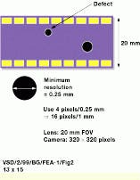
FIGURE 2.The camera, lens, and sensor size determine the minimum resolution and the field of view (FOV) required in a vision system application involving the inspection of a video tape for small surface defects. To find defects as small as 0.25 mm within an FOV of 20 mm, the camera and lens subsystem must provide a 4-pixel-per-0.25-mm resolution, or a 16-pixel-per-1-mm resolution over a 20-mm FOV. These parameters indicate that a camera with a minimum of 320 x 320-pixel camera sensor array should be used.
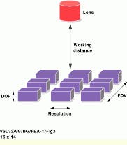
FIGURE 3.In many machine-vision applications, application space is confined or restricted. In this case, determining the lens selection calls for evaluating the working distance, or the distance from the lens to the object, the field of view (FOV), and the depth-of-field (DOF), which is the maximum object depth needed to focus properly.