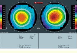
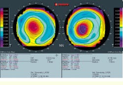
Image-acquisition system creates ophthalmic surface maps
Image-acquisition system creates ophthalmic surface maps
By R. Winn Hardin,
Contributing Editor
Eyeglasses and contact lenses are not the only devices available to people with nearsightedness, astigmatism, and other eyesight disorders. Ophthalmic surgeons are now routinely performing minor eye surgery to correct aberrations of the corneal lens, thereby refocusing incident light on the retina. Moreover, using small rotating blades or lasers, doctors can
easily remove tissue from the cornea to correct for surface aberrations on its anterior (rear) surface.
However, finding the eye ridges and valleys that cause light to scatter to unwanted portions of the retina is a complicated process. Currently, conventional methods used to guide surgical procedures rely on nomograms, or a standard set of eyeball shapes developed by the ophthalmic industry over many years. These methods, however, are not precise because every human eye is unique.
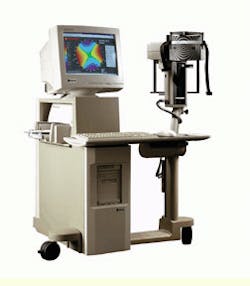
To aid physicians in customizing their refractive surgeries to suit individual patients, Orbtek Inc. (Salt Lake City, UT) offers the ORBSCAN PC-based image-acquisition system (see Fig. 1). Its proprietary hardware and software enable physicians to produce topographic maps of both the front and rear surfaces of the cornea as well as the front surface of its inner lens. Special ray-tracing algorithms can then be applied by ophthalmologists or their staff to extrapolate the map of the rear surface of the inner lens. After these maps of the optical surfaces have been constructed, the imaging system can develop a surgical plan for removing undesired tissue from the cornea. Consequently, physicians and patients are able to visualize in advance of surgical procedures where tissue should be removed and how the patient`s eyesight would be improved after surgery.
A reference point
Prior to imaging the patient`s eyes, the ORBSCAN imaging system is calibrated using a removable reflecting plate. The reflecting plate is placed approximately at the location where the patient`s eyes reside during evaluation and imaging. During calibration, the system`s two light sources bounce light off the reflecting plate. This pair of white-light slit lamps, which are positioned orthogonal to each other, straddle the charge-coupled-device (CCD) monochrome camera at 45. The image produced with the two beams of reflected light is captured by the CCD camera and sent via an RS-232 cable to a proprietary converter box.
According to Jack Savage, Orbtek chief executive officer, this box provides power to the ORBSCAN system and converts the CCD analog signals to digital, "so that we`re not tied to any particular computer." From the converter box the digital signals pass along another RS-232 cable to a PX500 frame grabber from Imagination Corp. (Beaverton, OR). According to Savage, Orbtek`s search for a frame grabber hinged on the board`s ability to funnel more than 40 images per second into the computer`s PCI bus without performing any image preprocessing. The images are then stored on a 7.3-Gbyte hard drive, where they can be saved temporarily or restored on an internal 100-Mbyte Zip drive from Iomega (Roy, UT). Orbtek`s marketing director Bill Sivill says that the capacities of the hard drives are changeable, depending on the system application.
The stored images are next returned to the computer`s resident 128 kbytes of RAM for processing. Proprietary software is used to detect the edges of the reflected light from the surrounding images. According to Savage, the system combines the distance from the reflecting plate to the CCD with the direction of the reflected lights to triangulate the position of the reflected edges in three-dimensional (3-D) Cartesian space.
Eye imaging
After the imaging system is calibrated, the patient`s eyes are evaluated. The patient places his or her head against a positioning pad and focuses on an internal red light that marks the position of the monochrome CCD camera, which is suspended above the patient`s eyes. According to Savage, there are no special specifications for the camera. This eye evaluation does not depend on a megapixel sensor for its high-resolution scans, but instead, relies on ORBSCAN`s proprietary software to create subpixel resolutions. This software can detect a few microns of variation in topographical distance from the initial reference point determined during the calibration step to the front (anterior) and rear (posterior) surfaces of the cornea, as well as the anterior surface of its inner lens.
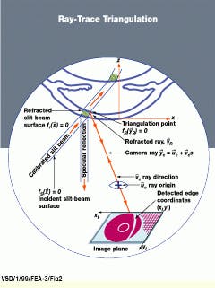
Upon activation, the ORBSCAN system moves the two slit lamps across the patient`s field of view from one side to the other (see Fig. 2). During this movement, the lamps travel in 40 small increments or steps across the several-millimeter width of the eye`s cornea. At each step, the system sends a signal along the RS-232 cable to the frame grabber and instructs it to acquire an image.
All 40 images are collected in approximately 1 s and fed rapidly into the PC`s hard drive. The computer contains an Intel (Santa Clara, CA) 400-MHz Pentium II processor and a 100-MHz bus for fast data transfer and manipulation.
After image acquisition and storage, the system software begins to threshold the individual images, looking for the two sickle shapes that represent the reflection of the slit lamps on the cornea and the small pinpoint reflections of the lamps off its inner lens. The leading edge of the sickles indicates the anterior surface of the cornea, whereas the trailing edge represents the posterior surface of the cornea. A third, albeit smaller reflection, indicates the anterior surface of the inner lens. Although the two lamps maintain a fixed distance between them as they scan across the patient`s field of view, the procedure is designed so that that the light reflections overlap across the 7-mm width that forms the center of the cornea, or the pupil of the eye. This procedure doubles the amount of data collected on the cornea and inner lens surfaces in this region.
According to Savage, the ORBSCAN imaging system is the first system that can image both the front and the rear surfaces of the cornea. It thus provides crucial data to ophthalmologists evaluating a custom refractive surgical technique, such as determining whether a follow-up or enhancement surgical operation is justified.
Image processing
After thresholding, the 40 acquired images are brought into the PC`s main memory. Here, they are correlated using proprietary reference points found in each image of the eye`s surfaces to adjust for small movements that occurred during the evaluation. In this processing, four reflections of the cornea and inner lens in each of the 40 images are compared to the known position of the reference reflection developed during the calibration procedure. Then, the ORBSCAN software triangulates the position of the anterior and posterior surfaces of the cornea and the anterior surface of its inner lens in 3-D Cartesian space (see Fig. 3).
To locate a point on the cornea`s anterior surface, an outer edge point is first detected to subpixel accuracy. From the video calibration, the detected edge point is then translated into the chief ray that entered the camera and formed the image. This camera ray is mathematically intersected with the slit-beam surfaces, which are precisely located during the calibration process. This process, which the company calls direct triangulation, results in an anterior corneal surface point located in x, y, and z space. The software generates data sets from each of the 40 images (the edges or points along the vertical plane where light interacts with each optical surface) and then combines them into a single, three-layer topographic map.
Next, the software combines the three surfaces to create an ORBSCAN fundamental display, which is a comparison of a "best-fit" sphere, representing the basic shape of the eye, to the 3-D topographic maps of the optical surfaces. Although it is similar to a nomogram, the best-fit sphere is based on the features that are unique to each individual eye. This best-fit sphere presents ophthalmologists with a baseline from which to determine the pits, peaks, and other imperfections that affect a patient`s sight.
In addition to illustrating anomalies on the surfaces of the cornea and inner lens of the eye, the fundamental display also shows curvature and thickness. Although thickness is far less of a contributor to poor eyesight than curvature of the cornea and lens, it can be a factor if a surgeon were to remove too much corneal tissue. The cornea would respond by forming an ecestia, or bump, to protect the tissue behind it, therefore defeating the purpose of the surgery.
After the software has developed the composite eye and topographic information, the surgeon has the option to permanently save these two files on the computer`s hard drive, or save all 40 images, data sets, and composites. For most ophthalmology applications, just the data sets and composites are saved, Savage says.
Follow the map
Based on the accumulated imaging data, the surgeon can produce a viable surgical plan. For additional help, two other Orbtek software modules, RAYSCAN and CIPTA (Corneal Interactive Programmed Topographic Ablation), enable the surgeon to map light rays as they pass through the anterior surfaces of the cornea and its inner lens to the retina. Ray-trace programs use the angle of incidence between the light ray and the optical surface, along with material thickness, refractive index, and laws of physics, to predict how light is focused by the lens. By examining the ray-trace diagram and working within the boundaries of natural cornea shape and minimum allowable thickness, RAYSCAN can deduce how the cornea should be changed to provide the tightest focus of light on the retina.
Once the optimal corneal shape is determined and converted into 3-D Cartesian space, the software module subtracts this shape from the existing shape and generates a third topographic map that represents the difference between the two corneal maps. The surgeon can then accept this map as the surgical plan, change it, or discard it.
Although a physician has the option at any time to make a hard copy of the topographic map and best-sphere shape, at this point, patient education becomes an important issue. To show patients how their eyesight would be affected by surgery, the system can transfer the effects of the pre- and postoperative focal-point-spread functions into two images and output these images to the system color printer. For example, the preoperative image might show how a scene would appear to the patient without eyeglasses. The postoperative image would simulate the same, but clearer, scene to the patient and represent, in advance, how the surgical procedure would improve the focal spread on the retina.
The CIPTA software takes the process a step further, converting the difference map into a program for directing the operation of a surgical excimer laser. Another software program called WAVE (Wavefront Ablation Vision Enhancement) also takes the posterior surface of the cornea into consideration. According to Sivill, this additional information provides an even better customized refractive surgical map because it takes all optical surfaces into consideration.
Although Orbtek is concentrating on ophthalmologic applications, Sivill adds that the company has performed some exploratory work on noninvasive surface measurements of metals and other surfaces. "We`ve done some work such as showing the topography of a dime to within microns," he says.
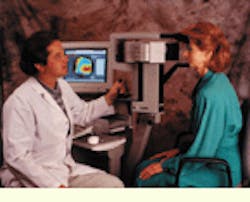
Technician uses ORBSCAN image-acquisition system to visualize the shape of a patient`s cornea.
FIGURE 1. The PC-based ORBSCAN image-acquisition system uses an illumination subsystem with two moving slit-lamps, a charge-coupled-device monochrome camera, and proprietary software to detect the x, y and z coordinates of the human eye`s refractive surfaces in three-dimensional Cartesian space (left). Equipped with this imaging-map information, both physicians and patients are able to visualize in advance of surgical procedures where tissue should be removed and how the patient`s eyesight would be improved after surgery.
FIGURE 2. In ray-trace triangulation, the planar slit beam diffusely reflected from the convex shell of the eye`s cornea appears as an annular arc in a video image. The outer and inner edges of this arc correspond, respectively, to the anterior (front) and posterior (rear) surfaces of the illuminated corneal volume.
FIGURE 3. Unlike previous corneal imaging systems, the ORBSCAN system`s fundamental display shows the topography of the anterior surface of the cornea (left) as well as the posterior surface (right).
