Applying pattern matching software in machine vision applications
Numerous methods can be used to rapidly localize objects within images.
Andrew Wilson, Editor
One of the most important steps in machine vision applications is locating an object of interest within the camera's field of view - a task that can be accomplished using pattern matching software. Such software tools can be deployed, for example, in systems where vision-guided robots need to pick and place randomly oriented parts from a conveyor. However, the task of pattern matching is not trivial since many variables such as an object's orientation, texture, color and features as well as variable lighting conditions, will dictate which type of pattern matching software is best suited for the task.
One of the earliest approaches to perform pattern matching is correlation. In this method, a template of a known good image is stepped over the captured image and a pixel-by pixel region comparison made. This comparison can be performed a number of different ways, such as computing the sum of absolute differences (SAD) - perhaps one of the simplest methods-or more complex methods such as normalized cross correlation (NCC).
Normalized correlation
NCC is useful in applications where the illumination of the object may vary due to lighting and exposure conditions. In this method, the mean image greyscale value is subtracted from each pixel value (i.e. normalized) before comparison with the result that the correlation will be invariant to global brightness changes. This technique is used in a number of software packages including the EasyMatch grey-level and color pattern matching library from Euresys (Angleur, Belgium;www.euresys.com), for example, that can automatically adjust the contrast and/or intensity of the template before comparison with the target image.
NCC is computationally expensive and this computation time increases as the size of the template becomes larger. To overcome this, pyramid-based hierarchical searching algorithms can be used to reduce the computation time required. In such fast NCC approaches, both the template image and the search image are hierarchical sub-sampled. Then by searching on the smallest sub-sampled image, the search space is reduced. After finding a matching point on this sub-sampled image, searches are then performed on higher resolution image layers in the pyramid to provide an accurate match between the template and search image.
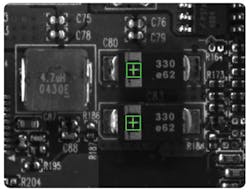
This is the approach taken by Matrox Imaging (Dorval, QC, Canada;www.matrox.com), for example, in its MIL Pattern Matching tool that uses a hierarchical search strategy to locate a pattern, including multiple occurrences, which are translated and slightly rotated, with sub-pixel accuracy. The tool performs well when scene lighting changes uniformly, which is useful for dealing with attenuating illumination (Figure 1).

In some machine vision applications, the object to be located will have grayscale characteristics similar to other objects in the scene, in which case grayscale pattern matching may not be accurate enough. If the object has color information that clearly differentiates it from the other objects, color-based pattern matching techniques can be used.
In such methods, the areas where the template and target image have a similar color spectrum are first located and then in these areas, greyscale pattern matching techniques such as NCC and geometric pattern matching can be used to obtain the final location of the object. Such an approach has been taken to identify a product from multiple variants and then to further inspect the presence of labels using the NI Vision library from National Instruments (NI; Austin, TX, USA;www.ni.com) see "Using Pattern Matching to inspect packaging prints" (http://bit.ly/1RRtcpx).
While such methods can overcome variations in lighting conditions, they are somewhat both scale and rotation invariant. To overcome this, a number of templates of the same image rotated and scaled to some degree can be generated and applied - a task that is more computationally intensive. Where objects to be located may be occluded or highly rotated or scaled, geometric pattern matching techniques are more effective.
Rather than comparing a grayscale template of an object, geometric features such as edge features and gradients of a template image are first detected and then characterized. These various geometric features are then used as a model to describe the template image. After an unknown image is captured, its geometric features are extracted and compared with those features from the template image to determine if the template image is present in the target image.
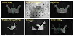
One of the first companies to develop such geometric pattern matching was Cognex (Natick, MA, USA;www.cognex.com) with the introduction of its PatMax software. By learning an object's geometry and looking for similar shapes in the target image, the software can locate objects despite any changes in angle, size and illumination conditions (Figure 2).
Today, many different companies offer software packages that incorporate geometric pattern matching techniques. These include the MIL Geometric Model Finder (GMF) tool from Matrox, HALCON from MVTec (Munich, Germany;www.mvtec.com) and Sapera Essential from Teledyne DALSA (Waterloo, ON, Canada; www.teledynedalsa.com). As well as obtaining geometrical features from template images, many of these software packages allow a template model to be obtained from a CAD file. However, how to extract the correct features from such CAD models has been the subject of on-going research for the last 25 years (see "A discourse on geometric feature recognition from CAD models" http://bit.ly/1n00tlv).
Texture analysis
Should an object lack discernible features, other approaches such as texture-based pattern matching can be employed. These include those that recognize and localize objects based on local point features such as the scale-invariant feature transform (SIFT), originally developed by David G. Lowe of the Computer Science Department at the University of British Columbia (Vancouver, BC, Canada;www.cs.ubc.ca see "Distinctive Image Features from Scale-Invariant Keypoints" (http://bit.ly/1YTfDEZ).
In developing its texture-based recognition software, Keyetech (Karlsruhe, Germany;www.keyetech.de), for example, has combined a Harris corner detector and the SIFT descriptor to compute features and perform pattern matching so that the complete task of object recognition and pose estimation takes approximately 15-20ms (see "Software targets high-speed pattern-matching applications," Vision Systems Design, February 2010, http://bit.ly/1YTi0Yz).
Multiple templates
All pattern recognition techniques depend on how well features from a template model compare with extracted image features. Thus, by training the system with a template that may be oriented at different scales, rotations and angles can be especially useful. In the past, this task was relegated the developer to the time-consuming task of presenting the system with templates at different geometrical perspectives and illumination conditions.
To overcome this, the CVB Polimago pattern matching tool from Stemmer Imaging (Puchheim, Germany;www.stemmer-imaging.de) first extracts characteristics from a template that are then saved in a model. Artificial views of the template are then automatically generated at different scales, rotations and angles to reproduce various positions of the scene that may be encountered (Figure 3).
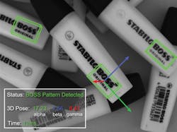
As a result, the algorithm learns the variability of these images and can thus recognize the teaching image in many different views. This makes the software particularly useful in robotic pick and place applications where parts may be presented at random orientations (see "Pattern recognition software targets pose estimation,"Vision Systems Design, September 2014, http://bit.ly/1F2CiuP).
3D too
While many pattern matching software packages operate on 2D images, recent work has led to the introduction of software packages capable of performing such tasks on 3D images. While 2D pattern matching techniques use template of a known good image whose features are compared with that of a target image, the same principle applies in 3D pattern matching techniques.
Here, stereo cameras, structured light, pattern projection or Time of Flight imaging cameras can be used to capture a point cloud model of a target image. This model is then compared with the point cloud of the target image - a feature useful in production environments where the features of captured 3D images must be compared with "golden templates" of known good parts.
This is the approach taken in Stemmer Imaging's CVB Match 3D software where a 3D image of a perfect sample is compared to a 3D image of a part under test. The algorithm operates on 3D point clouds and automatically adjusts position errors or tipping and tilts in all 3 axes. As the alignment is performed in software, there is no need for accurate part positioning and handling of the test sample.
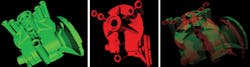
Similarly, Match3D from AQSENSE S.L. (Girona, Spain;www.aqsense.com) is a tool that aligns 3D surfaces of template and test parts with a best fit approach. Once they are aligned, both surfaces can be subtracted for obtaining a comparison between them (Figure 4). Aligning two 3D surfaces can be accomplished by mechanical means guiding the part under inspection with accurate positioning systems while a scanning system acquires the 3D shape. The mathematical alignment used in Match3D uses an iterative algorithm that iteratively "moves" the scanned surface closer and closer to the model's surface.
Companies mentioned
AQSENSE S.L.
Girona, Spain
www.aqsense.com
Cognex
Natick, MA, USA
www.cognex.com
Euresys
Angleur, Belgium
www.euresys.com
Keyetech
Karlsruhe, Germany
www.keyetech.de
Matrox
Dorval, QC, Canada
www.matrox.com
MVTec
Munich, Germany
www.mvtec.com
National Instruments
Austin, TX, USA
www.ni.com
Stemmer Imaging
Puchheim, Germany
www.stemmer-imaging.de
Teledyne DALSA
Waterloo, ON, Canada
www.teledynedalsa.com
University of British Columbia
Vancouver, BC, Canada
www.cs.ubc.ca
About the Author

Andy Wilson
Founding Editor
Founding editor of Vision Systems Design. Industry authority and author of thousands of technical articles on image processing, machine vision, and computer science.
B.Sc., Warwick University
Tel: 603-891-9115
Fax: 603-891-9297