Spacecraft carries to study Mars
Spacecraft carries to study Mars
By John Haystead, Contributing Editor
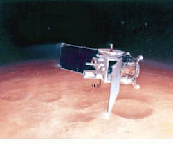
Built by Lockheed Martin Astronautics (Denver, CO) and managed by the NASA Jet Propulsion Laboratory (JPL; Pasadena, CA), the Mars Global Surveyor (MGS) carries several scientific instruments including the Hughes Santa Barbara Research Center (SBRC; Goleta, CA) thermal emission spectrometer (TES). This spectrometer is being used to conduct a planet-wide infrared (IR) survey of Mars` surface and atmosphere by studying the planet`s mineral composition, cloud formations, atmospheric dust, and weather patterns over the four seasons of a Martian year. It is expected to operate until the year 2000.
On Earth, all MGS mission operations and data analyses are being conducted by Arizona State University (Tempe, AZ). The collected thermal data are anticipated to help scientists determine the mineral composition of Martian areas as small as 3.5 square miles. Researchers also hope the TES will yield clues to the location of certain carbonate minerals that form only in the presence of water. Although there no longer is any water on Mars, the deposits might identify ancient shorelines where future missions could search for fossils.
Three in one
The thermal emission spectrometer comprises three instruments: a Michelson-interferometer spectrometer and two wide-band IR bolometers. Whereas the interferometer spectrometer covers the 6- to 50-µm wavelength range, the visible/near-IR bolometer measures reflected solar energy from 0.3 to 2.7 mm, and the IR bolometer collects surface-temperature information from 4.5 to 100 mm. Each instrument`s sensor provides a spatial resolution of 3 km at a distance of 350 km.
In addition to serving as a backup to the main spectrometer, the two bolometers are providing information about the physical properties and size of particles on the Martian surface and are attempting to measure any changes in Mars` polar ice caps. The state of the polar ice caps is related to the planet`s weather conditions. Therefore, by comparing the difference between the total amount of energy the ice caps emit with the amount of solar energy they reflect, scientists can determine whether ice is forming or evaporating. "Because cold surfaces emit significant amounts of energy above the 50-mm ceiling of the spectrometer, the broadband thermal [infrared] bolometer was added to ensure that all of the energy emitted is collected," says Phil Christensen, professor of geology at Arizona State University and MGS principal investigator.
System design
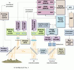
The TES consists of a pointing mirror, telescopes, sensors, interferometers, and an electronic-processing subsystem (see Fig. 1). Light energy is first collected by the spectrometer`s 6-in. primary mirror telescope, which sends the energy directly to the Michelson interferometer. A hole in the mirror also allows energy to pass through to a second 1-in. telescope servicing the two bolometers. This beam is directed to a 30-Hz, resonant-fork chopper drive that splits the beam between the two bolometers. Each TES instrument contains a single pyroelectric array that is hermetically sealed and backfilled with dry nitrogen.
Signals from all three instrument sensors (and housekeeping data from temperature and other sensors) are fed into several Harris Semiconductor (Melbourne, FL) HS-1840 radiation-hard analog multiplexers. These devices amplify and filter the signals and combine them into an analog data stream that is digitized by a Micro Networks (Worcester, MA) MN5290H 16-bit analog-to-digital (A/D) converter.
The A/D sampling rate is synchronized with the movement of the Michelson interferometer, at around 876 Hz, which is, in turn, determined by a fringe-detection circuit. This circuit forms part of the spectrometer`s dual Michelson (control/sensor) interferometer mechanism. The two interferometers are lo cated at either end of a linear motor drive that controls the move ment of the infrared interferometer`s beamsplitting mirror. Signals from the control interferometer`s fringe detector determine the speed at which the mirror will move over a 1-mm distance to produce double-sided interferograms at spectral resolutions of 5 and 10 cm-1.
The control interferometer uses two redundant neon-lamp sources. A narrow-bandpass filter isolates the emission line at 703.2 nm for fringe generation, with the continuum providing a quasi-white-light source for determination of zero-path difference. Each beam is collected by a silicon photodiode detector.
Operating as a 14-MHz crystal oscillator, the system timing sequencer receives fringe clock signals from the fringe-detector circuit and synchronizes to those clock signals, simultaneously generating a sampling command to the A/D converter.
Signal processing
After digitization, data are passed to a Texas Instruments (Stafford, TX) TMS-320C25 16-bit digital-signal processor (DSP) running at 7.5 MHz. "It is difficult to perform fast Fourier transforms with a 16-bit DSP. [The processor] made software development more complicated because overflows and shifts constantly need to be checked," says Arizona State University professor Christensen. Although Christensen would have preferred to use a 32- or 64-bit device, only 16-bit devices were available in space-qualified versions at the time the system was designed.
A shared-memory system links the DSP to the TES 80C86 command processor running at 4.8 MHz. The command processor can directly access both DSP and raw A/D timing-sequencer data. Says Rolph Keehn, SBRC senior engineer, "This key element of the design allowed two different processors running at different speeds to work together."
Raw data from the A/D converter are mapped into the DSP memory map that, in turn, are mapped into the 80C86 memory map. Although the 80C86 is capable of addressing up to 1 Mbyte of RAM, the system contains only 625 kbytes of RAM and 1/3 Mbyte of EPROM.
The command processor handles spectral editing functions and interfaces with and manages ground commands to set up various modes and gain configurations. "Because there is a limited bandwidth for transmission, we sometimes select particular detectors or use aggregate detectors," explains Christensen.
Sampling rates also can be adjusted. Whereas the full sampling rate is used over the warmest regions of Mars, data can be spatially and spectrally averaged at night and over the poles to decrease the volume of data. Data compression performed by the 80C86 delivers a losses compression ratio of 1.9:1.
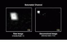
Several weeks after the launch in November 1996 of the MGS spacecraft and already 4.8 million km from Earth, the thermal emission spectrometer generated calibration data for the system`s processor (see Fig. 2). A spectrometer image of Earth from 4.8 million km was then assembled from bolometer-channel data. The raw image data were assembled from successive raster scans by the TES pointing mirror (see Fig. 3). With detailed knowledge of the TES field-of-view response from laboratory calibration data and computer processing, a deconvolved image of Earth was constructed with the field-of-view effects of the spectrometer removed.
Serial transmission
Designed by the JPL, the bus interface unit (BIU) provides the 1553 interface to the spacecraft`s main payload-data-system (PDS) computer. A dedicated 82C37A direct-access-memory chip handles the transfer of digital data from the command processor to the BIU. The BIU then transforms the data for serial transmission to the PDS via the 3.6-MHz 1553 data link.
Also built by the JPL, the PDS consists of two identical 1750A computers incorporating 128 kbytes of RAM and 20 kbytes of ROM. Only one computer controls the spacecraft, but identical software runs concurrently in the backup unit in case of emergency. The PDS transfers data packets from each of the spacecraft`s instruments in a sequential pattern, adding a header to identify the source before storing it in the spacecraft`s digital data recorder. The two solid-state recorders have a combined capacity of 375 Mbytes, allowing them to store data for up to 24 hours.
At scheduled in tervals, the spacecraft`s 8.4-GHz, 25-W transmitter sends data to Earth via its 1.5-m high-gain antenna at up to 85,333 bits/s. During the course of the spacecraft`s planned mission life, the system will transmit in the neighborhood of 83 Gbytes of data back to Earth.
Back on earth
Once received by NASA`s 34-m (112-ft) diameter Deep Space Network antennas located in the Mojave Desert (CA), Spain, and Australia, data are routed through the JPL to Arizona State University for processing. Before any scientific evaluation can be made, the data must be unpacked, reordered, and calibrated. The university is using two Ultra II computers from Sun Microsystems (Mountain View, CA) for the project, both of which are needed to run the complex atmospheric models developed by the Goddard Space Fight Center (Greenbelt, MD). The models must be run against each spectrum to remove atmospheric interference and to generate the atmospheric and surface spectrums.
The thermal emission spectrometer is not being used to take fast pictures of Mars. Given the spacecraft`s 9-km crosstrack field of view, a few hundred days of data are needed to compose an image of Mars from TES data. Multiple orbits are re quired and ap proximately 200 days of data to obtain full coverage at the Martian equator. "Al though we began collecting spectra in September 1997," says Christ ensen, "the spacecraft was initially in an elliptical orbit." Now, Christensen says, individual calibrated spectral data are providing initial information about atmospheric properties, water vapor, and the Mars surface.
FIGURE 1. The NASA thermal emission spectrometer (TES) will provide information about the properties and size of particles on the surface of Mars. Three instruments in one, the spectrometer consists of a Michelson spectrometer and two wide-band infrared bolometers. The thermal emission spectrometer image of earth from a distance of 4.8 million km has been assembled from bolometer-channel data. The raw image (left) was assembled from successive raster scans by the TES pointing mirror. With knowledge of the TES field-of-view response from laboratory calibration data and computer processing, a deconvolved image (right) was constructed with the field-of-view effects of the TES removed.
FIGURE 3. The thermal emission spectrometer (TES) image of Earth from a distance of 4.8 million km has been assembled from bolometer-channel data. The raw image (left) was assembled from successive raster scans by the TES pointing mirror. With knowledge of the TES field-of-view response from laboratory calibration data and computer processing, a deconvolved image (right) was constructed with the field-of-view effects of the TES removed.
FIGURE 2. First calibrated spectral radiance of the Earth (central heavy curve) from the thermal emission spectrometer is taken from a distance of 4.8 million km. The Earth`s CO2 absorption band is apparent at 668 cm -1, the ozone at 1000 and 1075 cm-1, and water vapor at both 200 to 550 and 1260 to 1650 cm-1. The lower heavy curve (near the x-axis) shows the noise-equivalent spectral radiance. Dotted curves show blackbody radiation at 215 K and 270 K.
Company Information
Arizona State University
Department of Geology
Mars Global Surveyor
TES Space Flight Facility
Tempe, AZ 85287
Web: www.asu.edu
Harris Corp.
Semiconductor Sector
Melbourne, FL 32902
(407) 724-7000
Web: www.semi.harris.com
Hughes Santa Barbara Research Center
Goleta, CA 93117
(805) 968-3511
Fax: (805) 562-4100
Web: www.sbrc.com
Lockheed Martin Astronautics
Littleton, CO 80127
(303) 977-5364
Fax: (303) 971-4902
Web: www.ast.imco.com/astro
Micro Networks Corp.
Worcester, MA 01606
(508) 852-5400
Fax: (508) 853-8296
Web: www.micronetworks.com
NASA Jet Propulsion Laboratory
Mars Surveyor Operations Project
Pasadena, CA 91109
(818) 354-4321
Web: www.jpl.nasa.gov
Sun Microsystems
Mountain View, CA 94043
(415) 336-2527
Fax: (415) 968-6396
Web: www.sun.com
Texas Instruments
Semiconductor Division
Stafford, TX 77477
(713) 274-2320
Fax: (713) 274-2324
Web: www.ti.com/dsps


