Machine vision delivers fire protection
Smoke, fire, and motion can be detected and recorded by neural-network- and CCTV-based system.
By George Privalov and Alexander Z. Shaykhutdinov
Point sensors have been the most common type of early fire warning detectors. These sensors measure the concentration of particles that are primarily products of fire. The particles could be ions directly produced by flames or heavier aerosol particles that are generally associated with smoke. Despite the different technologies involved, these sensors all measure the concentration of particles at the location of a sensor and therefore are called point sensors.
The most common point sensors are smoke detectors installed in homes. Measuring the light-scattering effect of smoke particles, these sensors trigger when the concentration of smoke in the measuring chamber exceeds that of a predefined threshold. Most smoke-detector failures, excluding purely technical issues such as dead batteries, are caused by smoke particles not reaching the device, which is therefore the limiting factor of point-sensor technology. Smoke may be carried away from the sensor by air movement or the smoke source may be too far from the sensor, so it takes too long for smoke particles to diffuse toward the point sensor.
Unlike point sensors, machine-vision systems can detect smoke from any distance within the field of view of the system camera. In addition, machine vision can detect the flames and give a remote operator the opportunity to see live video images from the location of the fire.
Technically, however, fire and smoke detection presents quite a challenge for machine vision. A practical machine-vision flame-detection system will have to identify flames in an unpredictable environment with changing lighting conditions and highly dynamic picture content. To add to the challenge, a fire has an irregular, constantly changing shape.
Machine-vision techniques that rely on static image processing are inappropriate for this task. To understand why, consider looking at still images of flames against a completely dark background. A setting like this hides important visual clues; for example, smoke can leave us confused and unable to apply common sense. However, when video of the flames-even in the same dark background-is shown, we do much better. If the same video is turned upside down, we are confused again. Therefore, the secret of human ability to recognize flames is the combination of motion and orientation. Machine-vision fire-and-smoke-detection systems such as the SigniFire system may use the same approach.
Machine Vision Detection
The SigniFire system separates an image into two distinct zones: one with steady and high brightness and the other with dynamic, constantly changing or flickering brightness. Flames always produce a bright emission core at the base, while turbulent air movement produces flickering at the top. The distinct pattern of these two zones is easy to identify with standard pattern-matching techniques.
The gas dynamics of flames can help us understand why we interpret the light sources with these features as fire. When the flame is small, such as a candle, it produces relatively little heat. Convection forces that move the gas upward inside the flame body are weak, so the gas flow remains slow and steady, or laminar. As the flame becomes larger, the convection forces become stronger, resulting in faster flowing gas. At some point, the speed will be fast enough for the gas flow to break up and ripple around the flames. When this happens, the flow becomes turbulent and chaotic, making the light-emitting plasma boundaries fluctuate and producing a flickering light emission.
Because the direction of gas flow is always against gravity, the flickering zone, or corona, tends to be located above the bright core. Although humans do not usually rationalize the physical nature of fire, this pattern is deeply embedded in our perception and thus can be exploited in the artificial intelligence of a machine-vision flame-detection system.
Flame Recognition
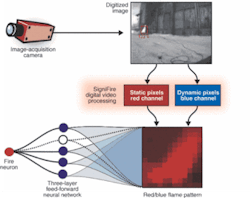
The task of flame recognition can be divided into three major stages. In the first stage, video frames are preprocessed to produce the so-called red-blue map of the image, reflecting the statistical characteristics of the image. Two independent parameters are computed for each individual pixel: the time-average brightness and the measure of the brightness fluctuations.
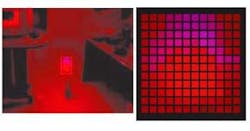
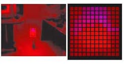
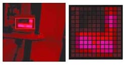
The SigniFire processing unit can produce a color-coded image, with the red channel assigned the time-average brightness and the blue channel assigned the fluctuations factor (see Fig. 1). The clusters containing high red and blue values are extracted and scaled to standard size in the second stage of flame recognition. In the third stage, a three-layer feed-forward neural network, trained to recognize the flames while rejecting nuisance light sources, analyzes the scaled clusters.
null
null
During the third stage, specific clusters containing both red and blue pixels are extracted, normalized to 12 × 12-pixel size, and fed into the three-layer neural network for pattern-matching. The "fire neuron" at the output of the neural network becomes excited if the cluster matches the flames. The neural network must be trained to accept only the patterns that are produced by flames, while rejecting the patterns that can appear from other dynamically changing light sources (see Fig. 2).
To train the neural network, a large number of video images are recorded and analyzed. These images include flames in different conditions such as light or wind, as well as other dynamic light sources such as flashing and moving lights, arc welding, and treetops with the sunlight shining through. Manual input provided by a human operator assigns the status of more than 12,000 images. The actual training of the network is achieved by minimizing the least-squares result of the human input versus the computed values of the network over the entire training set of 12,000 inputs. The weight values (total of 5821) produced by the minimization routine are embedded into SigniFire video-processing software.
SigniFire is implemented on a 2.4-GHz Intel Pentium IV platform running under Microsoft Windows. The system uses a Microsoft C++ compiler (Visual Studio .NET) and Windows XP operating system in headless configuration (no keyboard, mouse, and monitor). Threads are parallel execution threads within the SigniFire control program (multitasking within the task) as defined by Win32 documentation. The system can use any standard analog CCTV cameras, including black-and-white and color, and all available video formats (NTSC, PAL, SECAM).
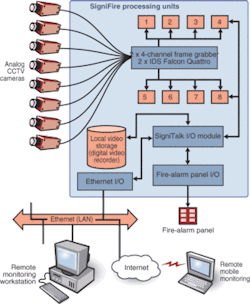
The system can simultaneously process up to eight analog video streams using two 4-channel Falcon Quattro frame grabbers from IDS-Germany (see Fig. 3). Captured frames are processed by software running in eight independent execution threads. All communication with the remote client is handled by the SigniTalk I/O subsystem connected to a computer network via Ethernet I/O module. On-event video sequences are captured for local storage on a digital video recorder. In addition, a dry contact interface is provided for communication with standard fire-alarm panels.
The SigniTalk I/O subsystem is a TCP/IP-based protocol that communicates with the system over the Internet/intranet by software module. Fire-alarm panel I/O hardware provides a means for directly wiring SigniFire into existing fire panels. Fire codes do not allow standard computer networks to be used as means of issuing alarms. Therefore, the LAN is used only to augment the system, while the primary means of delivering the alarm remains the dry contacts connected to a fire panel.
The SigniFire system is currently undergoing comprehensive tests at the US Naval Research Laboratory as a part of its program to develop a volume sensor that will provide situational awareness and damage assessment onboard Navy ships. As a part of the tests, the system is connected to a variety of cameras to determine the performance envelope. Additional trials are underway with a major electrical utility and with Factory Mutual, an industrial insurance provider that issues certificates for fire-safety equipment.
Vision-based fire-detection systems have clear advantage when protecting large-volume installations. Also, video-over-IP, while using existing computer-network infrastructure, provides situational awareness to CCTV surveillance systems unmatched by traditional panels.
GEORGE PRIVALOV is CEO at axonX, Baltimore, MD, USA, www.axonx.com; and ALEXANDER Z. SHAYKHUTDINOV is deputy director, Department of Gas Transport, OAO GazProm, Russia, www.gazprom.com.
Company Info
axonX LLC, Baltimore, MD, USA www.axonx.com
Factory Mutual, Johnston, RI, USA www.fmglobal.com
IDS Imaging Development Systems, Obersulm, Germany www.ids-imaging.com
US Naval Research Laboratory, Washington, DC, USA www.nrl.navy.mil
