Thermal imaging runs plastic-sheet heating
Associated Thermoforming Inc. (ATI, Berthoud, CO) makes automobile dashboards and computer-monitor enclosures from hot plastic sheets in a process called thermoforming. However, its existing "trial-and-error" production methods based on fixed, single-point temperature measurements limited its product offerings. ATI wanted to expand its business to include deep-drawn plastic parts. These parts require pattern or profile heating, in which plastic sheets are heated preferentially in certain areas to allow the plastic to stretch over taller features in the vacuum mold.
null
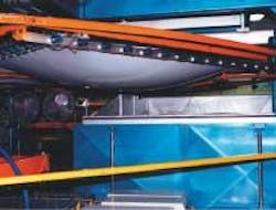
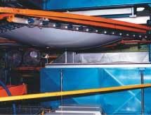
During thermoforming, plastic sheets a few mils thick (up to about 0.5 in.) and as large as 10 × 6 feet are heated in large radiant-heated ovens (see Fig. 1). After reaching the appropriate "forming" temperature (when the plastic exhibits the desired degree of pliability, or "rubberiness"), the hot plastic is quickly pulled from the oven and drawn into a vacuum mold. These molds turn flat pieces of plastic into a variety of products, some as flat and small as the soles of athletic shoes, others as topographically varied as bed liners for pick-up trucks with features of 18 in. or more in height.
To ensure that the sheets are heated to the proper forming temperature, ATI needed to control the temperature of the individual heating elements, or zones, within the oven. However, small openings prevented direct imaging of the oven heating elements or the sheet during heating. Imaging the heated sheet as it exited the oven proved to be the only viable solution, but the sheet needed to be quickly transferred to the mold before it fell below forming temperature.
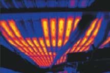
Therefore, ATI selected a linescan imager and software specifically designed for thermoforming applications. The line-scan thermal imager is sensitive to infrared (IR) radiation, allowing measurement of the two-dimensional (2-D) temperature distribution of each plastic sheet as it emerges from the oven (see Fig. 2).
FIGURE 2. Thermal imaging has been used as a preventive maintenance technique to check the individual heating elements in thermoforming ovens. However, the oven's small opening precludes the thermal imaging of sheets during the heating process. By imaging the sheet as it comes out of the oven, a technician can observe where the sheet elements are defective (top left) or operating at too low a temperature (center). The thick black line running diagonally through the image (right) is part of the oven's process of occluding the heating elements.
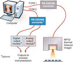
ATI selected the TF100 thermoforming imaging system from Raytek Corp. (Santa Cruz, CA). This system runs on a standard PC, a Model MP50 thermal linescan imager with associated power supply, an RS-485-to-RS-232 converter, and Raytek TF100 software specifically designed to support thermoforming applications (see Fig. 3). With this system ATI can store every thermal image of every manufactured part; store reference thermal images for every product; and show through numerical comparison, image subtraction, or multi-image display how a hot sheet compares to a stored reference heat pattern. With these data, technicians can adjust or repair individual heating elements in the oven to ensure the manufacture of high-quality plastic parts before the sheet reaches the mold.
null
Thermoforming challenges
Most thermoforming applications require uniform heating of the plastic sheet to the appropriate forming temperature. Technicians are limited to the manual control of heating elements and the time spent in the oven to uniformly heat each sheet because most ovens are not accessible to external sensors or thermal imaging.
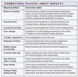
The manufacturing process is further complicated by the sheets themselves, which often vary in thickness from lot to lot. These variations mean that even for standard products, a particular lot may need more or less time in the oven to reach the proper forming temperature. Finding the right temperature for a sheet has been typically a trial-and-error process. Applying too much heat too fast can lead to blisters and bubbles, scorched areas, color changes, or excessive sheet sag, among other defects. Applying too little heat too long can lead to wrinkles, sag variations, and incomplete forming (see table).
Sheets with deep pulls or "draws" pose another set of problems. These sheets are heated more in the areas of the tallest features and less in others. Uniform heating means that, during molding, too much plastic will be pulled from the corners of the sheet, leading to wall thinning, cracks, gaps, and other defects.
John Nix, president of ATI, has successfully installed and used two TF100 systems in his plant, and he expects to purchase and install two more over the next two years. "We're really big on process control and we do some very difficult forming," he says. "Some parts could not be made without this technology."
Process control
ATI's systems use a laptop PC with a 200-MHz Pentium II processor, 64 Mbytes of RAM, and a 3-Gbyte hard drive for the TF100 software. Although the PC does not come with the TF100 package, ATI prefers to use a laptop instead of a desktop computer because ATI wants to easily move the imager from one thermoforming machine to another. The laptop is connected to the Raytek MP50 line-scan imager via an RS-232 serial cable. A Raytek serial data converter swaps the RS-485 formatted data coming out of the camera to RS-232 format. In this setup, the camera can send its ASCII data to the PC through a standard serial port, while retaining the ability to be located farther from the laptop than the 60-ft distance limitation of the RS-232 standard.
A second serial port is required if the technician wants to close the loop between the imager and programmable logic controllers (PLCs) or oven controls, such as when the application uses a continuous-feed oven in conjunction with a plastic roll or extrusion machine instead of sheets. Although ATI does not use this configuration, other Raytek customers use Raytek's analog- or digital-output modules to convert the electrical interface to other wiring configurations used for PLC control and communications.
An analog controller can handle one zone in an oven, essentially sending temperature data from each zone back to a PLC for the oven. Digital controllers are used for alarm signals when a zone temperature rises above or drops below set levels. For the analog controller, the TF100 software provides ASCII temperature data, but it is up to the user to port that data to PLC or display interface formats that are used on the plant floor. The digital alarm signal comes standard with the TF100 software. The serial data converter provides a wiring interface between the PC and the IR line scanner.
According to Raytek's marketing manager for process imaging systems, Alan Young, the company builds its own hardware converters for the RS-232/RS-485 converters and the analog and digital output modules to eliminate compatibility concerns. "The RS-232 and RS-485 converters adhere to electrical interface standards, not protocols. One of the things converters have to do is change state when they switch from transmit to receive. Some suppliers handle the switch in software; we do it in hardware. If we're in control of all the little features in the data converters, it is easier for us to ensure compatibility across many platforms without having to worry about whether a particular converter from a particular manufacturer is compatible or not," Young explains.
The MP50 thermal imagers installed at ATI use a single photodetector that is sensitive to the IR wavelength spectrum between 3 and 5 µm, but other spectral responses are also available. A spinning mirror collects the incoming IR radiation from the MP50 90° field of view at 256 specific points per scan and 48 scans per second. An internal analog-to-digital (A/D) chip converts the signals from analog to digital 8-bit values and then passes them into the imager's resident memory, which is capable of holding up to 700 lines in an 8-bit ASCII format. Because the camera does the A/D conversion and a single image occupies less than 2 Mbytes (typically, just a few 100 kilobytes), the camera works well with PCs that have relatively little memory (approximately 64 Mbytes), says Raytek's Young.
Closing the loop
The Raytek TF100 custom software converts the ASCII image data at up to 700 lines per image into a *.bin image format for storage, and it displays the pictures on the laptop's SVGA 800 × 600-pixel screen. "We use a binary image because that's the way we wrote the code, but many people want to do data crunching. They can store the images in ASCII and then import the data into a spreadsheet for manipulation," Young comments.
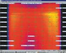
The image is then displayed in its original form or as a difference image showing the temperature variation between the collected image and the stored reference image. Both images show an overlay of the custom heating zones set up by the technician. Using this information, the technician can change the temperature of individual elements from the TF100 interface if the system includes the optional analog output controllers or at the oven itself without having to interrupt the thermoforming process or wasting plastic sheets because of over- or underheating (see Fig. 4).
Although Raytek has yet to port its thermal data to specific PLCs for additional thermoforming automation, Young says the company is actively looking at taking this next step. The next version of TF100 software will also incorporate object-linking embedding for process control (OPC) to more easily port TF100 data to umbrella manufacturing programs such as those available from WonderWare (Lake Forest, CA).
Requests for remote access to the image data have been relatively few, with the exception of OEMs. Raytek has already developed the OPC code for its OEM partners, but plans soon to incorporate it into user software, as well. In the meantime, users can access thermal images from the TF100 software via an Ethernet card in the host PC over their company's intranet. However, they cannot change the configuration parameters of the TF100 software. This requires that the TF100 software be shut down and changes made to a separate configuration file. Young says Raytek chose this approach for its simplicity, increased security, and to keep technicians from accidentally resetting zones or other parameters.
