System examines fiberoptic assemblies
PC-based imaging system integrates hardware and software to analyze captured images for fiber blemishes, chips, and cracks.
By Andrew Wilson, Editor
Fiberoptic connectors are widely used in telecommunications systems to increase the length of the transmission medium and to join distribution cables and fiberoptic transmitters and receivers. In the manufacture of fiberoptic connectors, the raw fiber is placed into a ferrule filled with epoxy. After curing the epoxy, the fiber is scribed and cleaved with the end of the ferrule and then polished. By using such manufacturing processes, optical-fiber manufacturers can build fiber pigtails (with a single connector attached to the fiber), patch cords (for network transceiver applications), and ribbon cables (a bundle of fibers with connectors at each end).
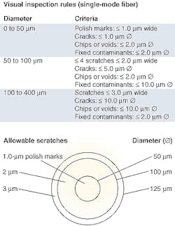
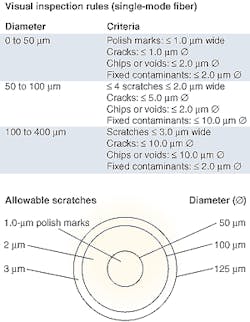
"After these connectors are made," says Douglas Wilson, president of PVI Systems (East Lyme, CT), "the end face of the fiber-termination must be inspected for scratches, cracks, chips, voids, and fixed contaminants." These defects can increase both the back reflection and the insertion loss of the fiber interface, as well as prevent proper mating of the connector. If the fiber has multiple scratches, for example, light reflected from the cleaved end of a fiber will increase and power throughput will decrease. As data bandwidths increase, minimizing the connectors losses associated with these defects becomes more critical to overall optical system performance.
"To inspect these defects," says PVI's Wilson, "fiberoptic-connector vendors have typically used microscope-based systems and manual defect-detection methods. As well as being time-consuming, this process is labor-intensive and subject to human errors." Such systems typically use low-cost specially designed fiber-testing microscopes, such as the FV-400 Enhanced Contrast System from Westover Scientific (Woodinville, WA), the Video Fiber Viewer from Prior Scientific (Rockland, MA), SpecVision from Krell Technologies (Marlboro, NJ), and the ME1000 Portable Fiber from Micro Enterprises (Norcross, GA) attached to a low-cost RS-170 or NTSC-based monitor.
To image the fiber, the FV-400 from Westover Scientific, for example, uses a blue light-emitting diode (LED) to illuminate the fiber and a built-in camera module that converts the reflected light from the surface of the fiber to an RS-170 video signal. Images are then displayed on an RS-170-compatible monitor. During operation, the technician places the fiber connector on the fiber viewer, adjusts the focus of the microscope to obtain a clear image on the monitor, and manually analyzes the image using a specification chart supplied by the manufacturer.
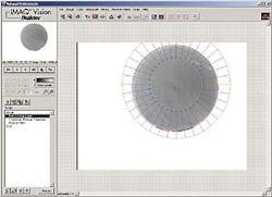
System automation"Just as overanalysis of each fiber adds cost," says Wilson, "underanalysis results in poor-quality products being shipped." And, to perform the fiber-inspection process manually takes 30 s or more per connector. By automating this process, the inspection time is reduced to about 10 s, resulting in reduced manpower required and a consistent, operator-independent set of results.FIGURE 3. The designers of the FiberQA-EFI system used NI's Vision Builder to prototype numerous algorithms. Vision Builder provides an easy-to-use, scriptable interface to IMAQ Vision tools. In this example, an image is opened, a circular edge tool from the Machine Vision menu is selected, and the object of interest is highlighted using an annular region of interest. Additional steps, such as thresholding (using a number of available methods including manual settings), blob analysis, particle filtering, and other image-processing functions may be added to the script.
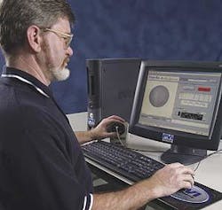
To semi-automate the process of fiber inspection, PVI Systems has developed a PC-based system that uses readily available fiber microscopes, frame grabbers, and standard PCI-based host computers. Dubbed the Fiber QA-EFI, the End Face Inspection System can use a number of fiber microscopes including those from Westover Scientific, Prior Scientific, Krell Technologies, and Micro Enterprises (see Fig. 2). Using the NI PCI-1407, a single-channel monochrome image acquisition board for RS-170 video from National Instruments (NI; Austin, TX), the RS-170 analog output from the fiber microscope is digitized into PC host memory.
To analyze captured images for scratches, cracks, and chips, PVI Systems uses NI IMAQ Vision Builder, IMAQ Vision, and LabVIEW software. Vision Builder, a scripting environment for IMAQ Vision that requires no programming, can be used to prototype gauging, alignment, inspection, and counting applications. It is used to rapidly generate LabVIEW code, called a Virtual Instrument (VI), using IMAQ Vision for LabVIEW.
"In the design of the FiberQA-EFI system," says Wilson, "several algorithms had to be developed using IMAQ Vision building blocks. For example, one of the FiberQA-EFI processing routines automatically locates the fiber within the field of view (FOV) and then finds the exact center and radius of the fiber." To illustrate how this can be prototyped in Vision Builder, an image is first opened and, using a circular-edge tool from the Machine Vision menu, the object of interest is highlighted. The parameters that control the performance of the circular-edge function can be modified in an interactive manner to achieve the desired results. Additional steps may be added, such as thresholding and particle analysis from pull-down menus. This results in a machine-vision script that implements the complete machine-vision operation to be performed (see Fig. 3).
Once this prototype script has been developed, Vision Builder can automatically convert the script to a LabVIEW VI. The programmer can then incorporate this VI directly into an overall application. Since it is the full LabVIEW source, the developer may also choose to edit the VI in the LabVIEW development environment.
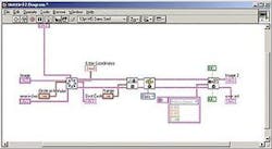
This LabVIEW diagram contains icons for the functions that are performed in the image-processing operation specified in the original Vision Builder script. This diagram is created using Vision Builder and then minor editing is performed to conform to PVI's coding standards. Front-panel controls and indicators and block-diagram constants are also created during the VI-build process.
FIGURE 4. After Vision Builder is used to prototype image-processing functions, it can automatically generate a LabVIEW diagram. After the image is captured, a second operation finds the center and radius of the image. The output then provides the center and radius information (Best Circle). Front panel controls, such as Range, which sets the lower and upper values for the threshold function, are also created. The second processing icon in this diagram performs the image threshold function. Lastly, particles found in the thresholded image are filtered based on area or other properties using the Particle Filter icon.
Figure 4 illustrates how Vision Builder was directed, through an interactive wizard, to build a VI that accepted an image input (Image) and provided controls for the IMAQ Find Circular Edge Tool and the IMAQ Threshold. The IMAQ Find Circular Edge Tool is a high-level image-processing operation that finds the coordinates and radius of a circular object in the image. The output of this function provides the center and radius information (Best Circle). The IMAQ Threshold function converts the image to a binary value at the threshold limits given in the (Range) input. Particle filter operations are then performed to remove particles of area less than five pixels. Although this example is straightforward, Vision Builder can be used to create more-complex algorithms.
After the system was prototyped using Vision Builder, additional IMAQ Vision and LabVIEW functions were incorporated to tailor the system for the specific fiber-inspection process. "While Vision Builder can be used to prototype a system," says Wilson, "incorporating other IMAQ and LabVIEW primitives into the diagram allows the system to be enhanced for more specific image-processing analysis functions such as inspecting for scratches, pits, and chips."
System operationOperator interaction with the FiberQA-EFI system involves calibration, configuration selection, focusing, and testing. Execution of the calibration function is recommended each time the system is started or after any change is made in the microscope. Configuration selection is performed each time a new set of specifications needs to be invoked, such as when testing a different part number. Focusing and test operations are performed for each connector. Additional functions, which the system can limit to higher-level access, such as for test engineers, allow the software to be configured for different test specifications.The system is calibrated by inserting a 'golden master' fiber with a known diameter into the video fiber viewer. The same fiber-locating algorithm used during testing automatically locates and measures the diameter of the fiber in pixels. This measurement is used to compute the conversion factor from pixels to user units, in this case, microns.
The operator selects the appropriate configuration for the connector under test. The configuration information, which includes zone geometries, defect definitions, and rules or limits, is automatically recalled from the FiberQA-EFI database. The type and size of defects can be specified, depending on the manufacturer's specific requirements. New configurations may be added to the database with different rules, defect definitions, and advanced processing settings. This flexibility enables FiberQA-EFI to be configured for almost any test specification.
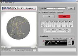
Once calibrated and configured, the FiberQA-EFI system can be used in an automated mode to test various fiberoptic connectors, including ST, SC, SMA, D4 types, and soon, MT connectors, depending on the adapter used on the microscope. After a technician attaches the fiber connector to the viewer, a focusing wheel is used to bring the end of the fiber into focus. Using a focusing-adjustment tool at the bottom right of the FiberQA's graphical user interface allows the technician to obtain the best-quality image (see Fig. 5). By correctly adjusting the positioning wheel, the technician can visualize in real time the focusing operation as it progresses from a poorly focused image (red) to a properly focused image (green). At the same time, the image captured by the frame grabber from the microscope is displayed on the left side of the graphical user interface. After each image is focused, the test function is invoked, and the number of scratches, chips, and particles are automatically classified in less than 10 s.
The FiberQA-EFI system is being used to semi-automate the production of fiber end-face inspection systems in tabletop environments. The system still requires that a technician load the fiber connectors into the fiber microscopes. "Initially," says Wilson, "fiberoptic vendors will purchase the FiberQA-EFI software/frame-grabber combination to convert existing manual-inspection stations from a qualitative to a quantitative system."
PVI Systems is making available software licenses to other OEMs. This allows systems developers to purchase the software in conjunction with third-party robotic systems and build fully automated fiber-inspection systems.
Company InformationKrell TechnologiesMarlboro. NJ 07751www.krelltech.comMicro Enterprises Inc.Norcross, GA 30071www.microenterprises.netNational InstrumentsAustin, TX 78759www.ni.comPrior ScientificRockland, MA 02370www.prior.comPVI SystemsEast Lyme, CT 06333www.pvisys.comRifocs CorporationCamarillo, CA 93012www.rifocs.comWestover ScientificWoodinville, WA 98072www.westoverscientific.com