Accordion interferometry puts the 'push' in propellers
If a military-submarine propeller's shape is off by as little as a few millimeters, it reduces the ships thrust, costing fuel and speed. When a submarine is brought into dry dock, the propeller is inspected using a fixed-tool-metrology system—a massive bridge-type metrology system costing millions of dollars and requiring the propeller be brought to the metrology lab or a less-accurate system with portable fixed reference grids.
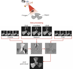
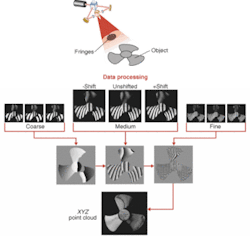
The new AFI 4000 from Dimensional Photonics Inc. (DPI; Southborough, MA, USA; www.dimensionalphotonics.com) uses a laser light source and movable diffraction grating to create an interference pattern on a propeller's surface. By moving the grating and acquiring multiple images showing different interference patterns, the AFI 4000 can produce a surface profile based on precise distance measurements for each pixel, creating a high-resolution "point cloud" that describes a propeller's surface.
White-light interferometric inspection systems are capable of quickly creating high-resolution surface maps. However, these systems have a limited depth of field that restricts their ability to inspect large parts with high resolution, according to DPI vice president of marketing Scott Ackerson. The AFI 4000 sends coherent light from a Lumex (Palatine, IL, USA; www.lumex.com) 650-nm laser diode through a proprietary diffraction grating and then a spatial filter that creates two separate point sources. These two point sources create an interference pattern with infinite depth.
The patterned light creates a visible fringe pattern on the surface of the propeller. A 12-bit gray-scale Atmel Grenoble TH7899M (San Jose, CA, USA; www.atmel-grenoble.com) CCD camera acquires an image of the interference pattern and feeds it to a National Instruments (Austin, TX, USA; ni.com) PCI1422 frame grabber. The frame grabber is located in a Hewlett-Packard (Palo Alto, CA, USA; www.hp.com) XW4100 workstation with 2.8-GHz Pentium 4, 2-Gbyte RAM, Nvidia (Santa Clara, CA, USA; www.nvidia.com) Quadro4 video card, 19-in. CRT, 160-Gbyte hard drive, and 4.7-Gbyte DVD+RW running under Windows XP Professional.
DPI FringeMaster software triggers a proprietary motion stage that moves the diffraction grating slightly and then acquires another image from the camera. The system is designed so that the stage moves very little for the first few images, essentially altering the phase of the reflected interference pattern. The grating is moved a greater distance so that the laser light passes through a grating with larger periodicity for the last few images to change the interference pattern itself. According to Ackerson, by combining phase and pattern contained in the intensity information from each pixel in each of nine images, the software determines the stand-off distance for each pixel with a minimum resolution of 50 µm for objects up to 2 × 2 m. The software then passes off the "point cloud" comprising 4 million 3-D data coordinates—one for each pixel—to a CAD comparison software program, such as PolyWorks by Innovmetric (Quebec City, QC, Canada).

