Vision/motion system tests printer rollers
Automated test system checks the surface integrity of thin cylindrical sleeves for printer rollers.
By Andrew Wilson, Editor
Desktop and short-run printers use different technologies to produce hard copies of documents. Many printing systems employ the basic principles of electrophotography: materials of opposite electrical charges attract, and certain materials are better conductors of electricity when exposed to light. For example, in the electrophotographic process, a photoconductive surface, often a cylindrical drum, is given a uniform electrical charge. An exposure device, such as a laser, creates an image of a document on the surface of the drum. After the surface of the drum is exposed, charge remains in the image area. Then, toner of the opposite charge is introduced to the surface and is attracted to the charged image area, which produces a visible image on the drum surface. To transfer this image to paper, the toner is either transferred via a transfer roller or directly by electrostatic attraction to paper. The image is then fused to the paper by heat and pressure.
Different types of cylinders and rollers are used. These include photoconductive cylinders, image-transfer rollers, and fuser rollers. To manufacture these rollers, a thin cylindrical sleeve is attached to a master cylinder using a vacuum. In this way, master cylinders can be easily refurbished after use by replacing their thin cylindrical sleeve.
Nicks and cracks
After manufacturing, master cylinders must be checked for defects such as nicks, cracks, and scratches to ensure that high-fidelity images will be transferred to the printing system. To perform this operation manually, the cylinders, which can be as large as 8 in. in diameter and 14 in. in length, are inspected visually or under a microscope. Print testing is also a common method for ensuring quality but is costly because it requires that the cylinder be installed in a print engine during testing.
"Manual inspection can be tedious and time-consuming," says Kate Johnson, director of engineering at ImageXpert (Nashua, NH, USA), "and results are difficult to quantify and track." Recognizing these problems, a large manufacturer of photoconductive cylinders approached the company to develop a fully automated test system capable of reducing inspection time to approximately five minutes while providing characterization and classification of cylinder surface defects.
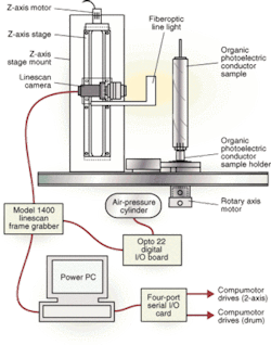
"In designing the system to inspect printer rollers at the desired rate," says Johnson, "we needed to combine both motion control and machine vision using off-the-shelf products that we were already familiar with (see Fig. 1). Because there was an expressed need to rapidly place and remove the thin cylindrical sleeves," says Johnson, "it was necessary to use a mandrel specifically designed for these sleeves and include it in a motorized fixture."
ImageXpert chose a dc power supply and a 6-in. fiberoptic line light from Schott-Fostec (Auburn, NY, USA), mounted on the z-axis next to a camera, to illuminate the cylinder sleeve surface during inspection. Once mounted on a z-axis stage from Newport Corp. (Irvine, CA, USA), a Spyder 1k digital linescan camera from Dalsa (Waterloo, ON, Canada) is moved to the base of the cylinder sleeve. After the cylinder sleeve is properly placed, an air-pressure cylinder under control of an I/O board from Opto 22 (Temecula, CA, USA) holds the thin cylindrical sleeve to the mandrel during inspection.
Cylinder rotation
Once in position, the cylinder sleeve must be rotated to digitize a complete sweep of its surface. The drum axis is rotated using servomotors from the Parker Hannifin Compumotor Division (Rohnert Park, CA, USA). In turn, the servomotors are driven by a Compumotor servomotor controller using an SX Pro Serial Card from Keyspan (Richmond, CA, USA). This PCI-based card is housed in the host PowerPC-based computer and provides up to four serial ports that support asynchronous or clocked asynchronous RS-422/RS-232 communications at data rates to 1 Mbit/s.
After the z-axis stage is positioned at the base of the drive setup and the drum is rotating, an image of the cylinder is captured using the camera and ImageXpert's 9.1 software. This software was developed using the Acuity 9.2 Power PC-based software, ImageAnalyst, and a Series 1400 linescan frame grabber from RVSI Acuity CiMatrix (Nashua, NH, USA). After one sweep has been imaged, the camera is moved along the z-axis stage so that the next image can be captured. For test-system efficiency, the first image is processed while the second is being acquired.
"By providing a slight overlap between scans on the z-axis," says Johnson, "complete two-dimensional image analysis of the cylinder plate can be performed using our image-analysis software."
GUI design
Stephen Parker, director of manufacturing at ImageXpert, used the flexibility of ImageXpert software to create a user-friendly graphical user interface (GUI). "In the design of this user interface for the system," Parker says, "we needed to keep the number of controls to a minimum while providing the user-critical process information."
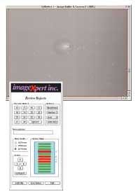
The user interface uses just a few point-and-click controls to operate the combined imaging and motion-control system. The user first loads the sample and then runs the test. During testing, a sleeve map is presented on the GUI that shows the status of the inspection as it progresses (see Fig. 2). Users can also review the types and sizes of cylinder defects on the GUI as, or after, the inspection progresses. Images of each defect can also be reviewed. Defect information is stored in a file and logged with the results of each inspection.
"With the ImageXpert software, it takes approximately one day to tailor the system for different sizes and types of cylinders to be inspected," says Parker. And, once the system is installed, significant defects can be identified by correlating the defects found on the cylinder with repeating defects in the finished print from a completely assembled printer. "In this way," he says, "manufacturers can optimize the quality of the cylinder sleeves by ignoring defects that may have no impact on the final output of the electrophotographic printer."
Company Info
Dalsa www.dalsa.com
ImageXpert www.imagexpert.com
Keyspan www.keyspan.com
Newport Corp. www.newport.com
Opto 22 www.opto22.com
Parker Hannifin www.compumotor.com
RVSI Acuity CiMatrix www.rvsi.com/acuitycimatrix
Schott-Fostec www.us.schott.com


