Laser scanner speeds molding process
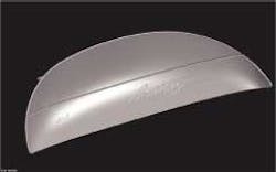
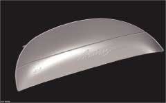
Engineers at Hunt Machine and Manufacturing (Talmadge, OH; www.huntmachine.com) were recently contracted to build a mold of an interior trim part for an automobile. "We were given this task without any computer-aided design (CAD) data," says president Dave Hunt. The company that built the original tooling had taken CAD data and combined it with pattern makers' models to make the original mold, but both the models and the CAD data were no longer available. In addition, the part was physically flexible, which ruled out a contact measurement method (CMM) to determine its geometry. Worse, because CMM measures single points at a time, it would have taken a very long time to collect enough points to reproduce the contoured geometry of the instrument panel part.
As a result, Hunt sent the part to NVision (Coppell, TX; nvision3d.com). This company used a ModelMaker laser scanner to produce a surface model of the part. The mold builder then made modifications requested by the OEM, produced several rapid prototypes for verification, and designed a new mold. The ModelMaker system captures surface shapes in real time at more than 23,000 points per second.
"We reconstructed the instrument panel in our facility so we could mount the part as it would be in a vehicle," said Bill Bonner, director of sales and consulting for NVision. "All sides of the part were scanned with the ModelMaker in one day," he adds.
As a technician moves the system sensor over the surface of the part, a dedicated PCI interface card translates the video image of the line into three-dimensional (3-D) coordinates. This process creates a dense cloud of 3-D data that describes the surface of the part. The result is a point cloud consisting of more than 1 million points. Lettering on the part is separately scanned using a ModelMaker W35 scanner. NVision used Surfacer software from EDS (Plano, TX; www.eds.com) to automatically generate surfaces through the point cloud. On the part's most critical front surface, NVision used the ultra-violet blend method, which builds the surfaces from cross sections in both the x and y directions.
Hunt Machine provided the resulting CAD file to a design firm that converted it to Pro/Engineer CAD format developed by PTC (Needham, MA; www.ptc.com), performed modifications requested by the customer, and provided an Initial Graphics Exchange Specification surface-model file to Hunt Machine. This file was then read into a Unigraphics CAD system, also from EDS. The surface model was converted to a solid model, and a prototype was produced using a stereolithography system. The customer examined the prototype and requested several additional modifications. The goal of these changes was to improve the fit of the part within the instrument panel. Hunt Machine made these modifications and provided a new prototype.
Engineers then designed the mold to produce the new design. "It would have taken 28 weeks to do the job using CMM compared to the 16 weeks that was required with laser scanning. The main reason for this time improvement is that laser scanning generates a detailed point cloud in minimal time while CMM points must be collected one by one. Using the ModelMaker, a more accurate mold was produced since the million-plus points generated was used to produce a solid model that accurately reflected the contours of the part," says Hunt.

