Using vision sensor technology to calibrate gas flowmeters
For almost a century, rotary gas flow meters have been used for measurement and billing of commercial and industrial gas loads. In applications where measurement of gas must be made from the well to the burner, accuracy, dependability, and low maintenance are of key importance. To meet such demands, companies such as Roots Meters and Instruments, DMD Roots Division of Dresser Equipment Group (Houston, TX) build rotary positive displacement gas flow meters using precision machined two-lobe impellers encased within a rigid measuring chamber.
According to Walter Ferguson, a Senior Project Engineer with sister-company Dresser Instrument Division (Stratford, CT), measurement accuracy in such designs is not affected by changes in gas specific gravity, pressure, or fluctuating flow. "However, changes in temperature of the flowing gas affects the correction factor applied to the standard volume since the gas expands or cools as temperature increases or decreases from its base temperature, which is normally 60o F," says Pandu Nayak, Manager of Product Engineering & Technical Services at Dresser Equipment Group. "There is an approximate 1% change in volume for every 5°F, and with gas normally sold at a 60°F, it is important to compensate for gas when deviations exceed an acceptable error. Most gas being sold at flowing temperatures below an average of 60°F will apply a correction factor for this error," he adds.
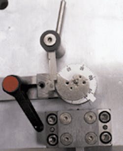
Figure 1: Gas temperature is measured in a gas flow meter by using a helical bimetallic coil or probe located in a sealed temperature well at the meter inlet. Attached to the bi-metallic thermocouple, a calibrated working cam determines the temperature of the gas at any specific point. To measure this, a mechanical arm driven by gas flow is moved periodically against the working cam. The distance between the initial position of the mechanical arm and the rotating cam determines the amount by which the gas flow must be compensated.
To perform this compensation, a mechanical computer with a spiral bi-metallic coil or probe is located in a sealed temperature well at the meter inlet. Attached to the bi-metallic coil is a working cam calibrated in degrees Fahrenheit designed to compensate for temperature changes determines the temperature of the gas at any specific point (see Fig. 1). The correction factor for changes in volume is designed into the cam. As the temperature changes the bimetal coil places the cam in a specific location for the given temperature and To measure this temperature, a mechanical "computing arm" driven by gas flow is moved periodically against the working cam. The distance between the initial position of the mechanical arm and the rotating cam determines the amount by which the gas flow must be compensated.
"Since the temperature probe determines the accuracy to which the gas flow is metered," says Ferguson; "calibration of the accuracy of the device is of utmost importance." In previous generations of gas flow meter, this procedure was performed manually. Operators would first place each probe in a bath of +60°F for 45 seconds. After measuring the angle of rotation against a fixed pointer built into the probe, the angle of motion was manually recorded under a halogen magnifying lamp.
After the angle is recorded, the probe is then placed in another bath at -20°F for 45 seconds and the angle again recorded. Finally, a third bath is used to bring the temperature to +100°F for 45 seconds and the temperature and difference angle recorded for the last time. In this way, the rotation of the cam head can be measured from 60°F to -20°F and from 60°F to 100°F.
"Using operators to manually record the different angles," says Ferguson, "it was possible to obtain an subjectible accuracy of typically +/- 2.5 angular degrees." However, the target accuracy with the vision system is +/- 0.5 angular degree. To accomplish this, Ferguson and his colleagues decided to automate the process using the In-Sight vision sensor from Cognex (Natick, MA).
Automating the process
In-Sight consists of a DSP-based processing unit, a 640 x 480 x 8-bit progressive scan CCD camera, a Nintendo-like programmable, and a library of vision software tools. With In-Sight, applications can be created, tested, and deployed using the system's In-Sight's vision spreadsheet interface. To do so, applications are configured by selecting tools and parameters from menus using the Nintendo-like controller. In-Sight then automatically enters tool results into worksheet cells that can be linked together to perform functions such as locating or measuring parts.
"In performing an automated inspection of the probe," says Bonnie Solbo, Senior Technical Support Engineer at Cognex, "The In-Sight system must first be trained to recognize the pattern of the cam. This will be needed as a fixturing mechanism for subsequent tool placement. The tools will move as the cam rotates." To do so, the PatFind tool is first trained on the cam by drawing a box around it using the control pad. Once recognized, PatFind software can determine the location of the cam at any angle.
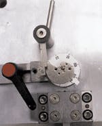
To determine the angle of motion that the cam has turned through after immersion, a number of reference points needed to be determined. "One point of reference needed is the center of the probe. To properly determine this point, a best fit circle of the outside of the probe needs to be created," says Solbo, "It is found by finding three points around the perimeter of the dial using edge analysis tools." These are highlighted using the systems controller and highlighted in red (see Fig. 2). Once determined, the edge analysis tools are used as inputs into the Circle from Points Fit tool to define a green circle around the outside perimeter of the probe. The tool also gives the center point of the resulting best fit circle.
Once the cam position and reference is known, the degree of motion of the cam with reference to other trained parameters must be determined. To do this, the system is then trained to identify the fixed pointer previously used to manually calibrate the probe. Located outside the housing of the probe, this provides a stable reference point with which to measure cam angle. The changing point will either be the tip of the cam (highlighted in red) and/or the dial tab located opposite provide the two other reference points.
Figure 2: To measure the angle of motion of the probe, the center point of the cam is determined using In-Sight's best fit circle measurement tool. Once determined, the information provided by the relationship between the pointer's intersection with the centerpoint and the cam tip's relationship with the centerpoint form the angle of motion that the probe has moved through. This angle is then measured to an accuracy of +/-0.5 angular degree by In-Sight and used for probe calibration.
To measure the angle of motion, the center point of the cam shaft is determined using In-Sight's best fit circle measurement tool. Once determined, a line to line measurement tool can use the information provided by the relationship between the pointer's intersection with the centerpoint and the cam tip's relationship with the centerpoint to form the angle of motion that the probe head has moved through. This angle is then measured to an accuracy of +/-0.5% angular degree by the In-Sight system.
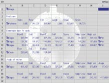
"While the inspection capabilities of the In-Sight system are impressive," says Ferguson, "we also need to move measured imaging data to Microsoft Excel for statistical analysis." Since In-Sight unit is a stand alone system, captured and measured data can be transferred from the In-Sight's serial port and into the serial port of a host PC. "At present," says Solbo, "there is one way to get information like this to transferred from the In-Sight system to a user's PC and that would be serially. The data can be transferred through to VB or some other application that handles serial communication, then pushed into to a Microsoft Excel spreadsheet using a DDE tool also available in VB or other application." —ANDREW WILSON


