COTS-based radar tracks airport grounds

Incorporating off-the-shelf digitizers and workstations, a fully automated ground-surveillance radar system reduces the workload of air-traffic controllers.
By John Haystead,Contributing Editor
At all major airports, air-traffic controllers deal with inbound and outbound aircraft, ground traffic on runways and flightlines, taxiing aircraft, and airport maintenance, fire, oil, and support vehicles, among others. As well, they must watch for any possible intrusion by unforeseen hazards, such as illegally parked or moving vehicles and airplanes. These are all daunting tasks, particularly when weather is poor and controllers have limited visibility of ground operations. Yet, today, many airports, both large and small, do not have an automated warning capability for ground operations.
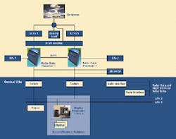
FIGURE 1. To ensure continuous operation in the critical airport ground-surveillance application, the ASMR architecture incorporates redundant systems and interconnects throughout, including redundant transceivers, radar data processors, LANs, and display processors. The XCVR monitor can switch to the backup transceiver unit within microseconds.
To meet most of this need, Raytheon Air Traffic Control Business (Lexington, MA) has developed an advanced surface-movement radar (ASMR) capable of locating objects as small as one square meter. This radar system can identify and track all airport ground traffic and automatically alerts controllers to potentially hazardous situations.
"Although other ground-traffic-monitoring systems were available, they were not based on mature technologies and tended to be expensive," says Peter Dunham, Raytheon deputy manager. "By using computer off-the-shelf-based hardware," he adds, "we produced a system that cost one-quarter of competing system prices."
COMMERCIAL COREThe core ASMR design was derived from the Raytheon Pathfinder series of commercial maritime radars with modifications to serve the airport ground-surveillance application. These included changing the system's operating frequency to the aviation frequency band of 9.0 to 9.2 GHz and incorporating frequency-hopping techniques for improved target detection during precipitation. In addition, designers shifted the marine radar's magnetron-based design to an all-solid-state unit that provides improvements in reliability and life-cycle costs, according to David Bloomstran, Raytheon's manager of airport systems.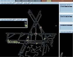
FIGURE 2. At Boston's Logan International Airport, aircraft wait to enter the departure end of runway 22R. Across the top of the display are the controls for runway configuration, mode (operational or playback), current transceiver being accessed, status of both RDPs (one is not functional), and status bar indicating the current highest level alert. Three views of the airport are displayed including a plan view, view of approaches to runways 22L and 22R, and a view of the approach to runway 27.
In the ASMR parallel-feed array-beam antenna, energy is fed into the center of the antenna and through a series of divider networks, culminating in an array of 250 equidistant radiating elements across the antenna. Because the paths are all of equal length, the wavefront leaving the antenna is parallel to its surface and of uniform shape. The ASMR also maintains its pulse shape over a wide frequency spectrum, an important consideration for a frequency-agile system. As opposed to slotted waveguides, where pulse distortions occur around 100 MHz, the main beam of the ASMR is independent of operating frequency with no significant short-pulse distortions of the bandwidth in excess of 700 MHz.
Pulsed radar systems for aircraft and naval navigation primarily use a single directional antenna to transmit and receive microwaves. These microwaves are transmitted and reflected by objects in the path of the beam where they are received by the radar unit, processed, and converted into radar images. When sending, the antenna must be connected to the transmitter; when receiving, it must be connected to the receiver. This is accomplished by switching from one to the other and back again in the fraction of a microsecond between pulses. The distance of the object from the radar source is determined by measuring the time required for the radar signal to reach the target and then return. The direction of the object with respect to the radar unit is determined from the direction in which the pulses were transmitted. In operation, the beam of pulses is rotated at a constant speed over a sector at a constant rate.
REDUNDANT TRANSMIT/RECEIVETo power and receive the radar signals, the ASMR uses two redundant radar transceiver units, with one unit in active mode and the other in standby mode (see Fig. 1). Signals from both the on-line and standby transceivers are passed through a separate transceiver monitor (XCVR monitor) unit that checks the output of the on-line transceiver for conditions such as low power and over-temperature. The XCVR monitor automatically switches to the back-up transceiver whenever the active unit is not operating within specifications.Incorporating class-AB linear amplifiers, the solid-state transceivers deliver 60-W peak-power output, with the output frequency programmable in 1-MHz steps across the full 9.0- to 9.2-GHz frequency range. Frequency hopping at four independently tunable frequencies provides improved detection and performance during degraded weather conditions.
A dual-pulse system, the ASMR uses a gated carrier-wave pulse for short-range and low-frequency modulated chirp (35 MHz) for long-range coverage. With a scan rate of 60 rpm and a pulse-repetition frequency of 4 kHz, the system has a tracking range of 0.1 to 4 nautical miles (nmi) and an azimuth resolution (at 1 nmi) of 50 ft. The transceiver units interface to the antenna via a waveguide circulator that isolates the transmitter from the receiver and use PIN diode-based input protection and low-noise amplifiers. The receivers also use double-balanced mixers and dual down-conversion techniques to provide an image with a >50 dB signal-to-noise ratio and spurious rejection of greater than 60 dB.
"If you have large objects or targets such as buildings close to the radar antenna, the return signal will also be large, and if it is allowed to enter the receiver, it will saturate the system," says Bloomstran. "To prevent this, a programmable sensitivity-time-control (STC) function is applied to the return signal to attenuate those signals close to the antenna. With a 75-dB dynamic range, the receivers, together with STC, allow for operation in the linear response portion of the receiver-transfer curve for a variety of clutter/target ratios without saturation. The receiver recovery time from a saturated state is 100 ns.
The transceivers' digital control units are built using field-programmable gate arrays and handle all the timing, monitoring, and control functions of the radar. An RS-232 serial interface links the controllers to the radar data processor where a graphical user interface provides for remote control, monitoring, and transceiver parameter setup.
The digital controller continually monitors the radar operating mode (short/long pulse) and automatically switches the antenna return signals to either a surface acoustic-wave-based pulse-compression circuit for long-pulse or a matched filter for short-pulse processing. This compressor/filter output is then passed through a log detector that outputs the detected video signals. Radar status data are superimposed on this signal, and the composite video containing azimuth, status, trigger, and analog video are passed to the radar data processors via 50-Omega coaxial cable.
OFF-THE-SHELF IMAGINGData from the active transceiver are received by both radar processors, with one unit serving as the on-line system while the other is in "hot-standby" mode. These data are simultaneously processed by both units, which are linked to each other via a high-performance parallel interface to maintain a single set of track identification signals. The sustained data rate between the machines is 800 Mbit/s.Silicon Graphics Inc. (SGI; Mountain View, CA) Origin 2000 UNIX workstations incorporating Acqiris (Geneva, Switzerland) digitizer cards are used as radar data processors (RDPs). The analog video signal from the radar is first converted to 8-bit data by the Acqiris card before being passed to the Origin 2000 CPU. All signal-processing functions including detection, plot extraction, tracking, and alert logic computations are then handled by the system CPU.
Written in C++ language, the ASMR tracking and conflict-alert software was jointly developed by Raytheon and MIT Lincoln Laboratory (Lexington, MA). Thresholding algorithms remove clutter such as lights and signs from the raw video. Constant false-alarm-rate processing algorithms continually update and adjust detection parameters to changing weather conditions.
Track reports are derived from the extracted plots using Interactive Multi-Modal Kalman filtering combined with an algorithm derived from the Raytheon Hawk-missile program. The system can track up to 200 objects, expandable to 1000 by adding more 64-bit processors to the SGI workstations. The conflict-alert software differentiates between routine status reporting and potentially serious conflict situations.
The RDPs deliver raw video, track reports, and alerts to multiple controller display processors and monitors located in the control tower via two independent local-area networks (LANs; see Fig. 2). The use of dual LANs ensures connectivity to either RDP. Status-monitoring software running in the display processors determines which RDP to access.
Each controller display position consists of a Silicon Graphics O2 UNIX workstation and a General Digital (Manchester, CT) daylight-readable, 20-in., 1280 x 1024-pixel flat-panel display. The base ASMR system includes three display positions but can drive up to 16 stations without hardware or software modifications. The Motif-written display software can accommodate the 16 windows available on each display. All data sent to the controller displays are buffered, time-stamped, and recorded on standard SGI tape drives.
The ASMR system is in use in Milwaukee, WI, where it is being evaluated and tested by the US Federal Aviation Administration. A follow-on system, the ASDE-X, operates in the X-band and combines frequency diversity with circular antenna polarization to improve performance during inclement weather.
Company InformationAcqiris Geneva, SwitzerlandWeb: www.acqiris.comGeneral Digital
Manchester, CT 06040
Web: www.gendig.com
MIT Lincoln Laboratory
Lexington, MA 02420
Web: www.ll.mit.edu
Raytheon Air Traffic Control Business
Lexington, MA 02421
Web: www.raytheon.com
Silicon Graphics Inc.
Mountain View, CA 94043
Web: www.sgi.com