Minirobot monitors sintering with vision

Vision-guided minirobot and PLC place parts before a 200-ton coining press strikes.
By David Lieberman
Sintering, the process of turning powdered metal into a strong, dense solid without melting it, is an increasingly popular method for creating rugged precision parts, including gears, valve seats, rotor assemblies, tools, and various kinds of structural components. Typically, the material goes through one or more multithousand-degree heating stages in a tightly controlled environment, in addition to one or more compression stages. This results in products with very strong molecular bonds and hardness on the order of 50 to 60 Rockwells.
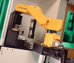
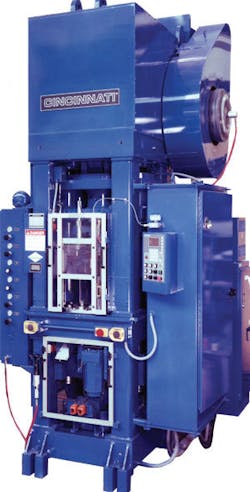
Moving the parts between different pieces of sintering equipment can be quite labor-intensive. McAlister Design has developed and installed a system that automates the process, thus speeding manufacturing and maximizing operator productivity (see Fig. 1). It moves parts between a sintering oven and a coining press, which typically eliminates warping that may have occurred in the previous heating cycle and can modify some feature of the part. The coining press is a Cincinnati 200, which strikes with up to 200 tons of pressure (see Fig. 2).
null
SYSTEM SETUP
The main components of the McAlister system are a PLC from Allen Bradley, a robot and a companion robot controller box from Fanuc Robotics America, and a PC running Windows XP with Fanuc vision software. Traditionally, human operators feed parts to the Cincinnati 200 press before it strikes, manipulating each part so it fits into the tooling that resides on a multiposition turntable in the press. Loading such a machine presents certain dangers to the operator and raises ergonomic concerns, as well. Given the space considerations of the operation, automating the transfer of parts from the sintering oven to the coining press required a smart conveyor belt and a small, fast, accurate robot with vision.
“Robots can manipulate parts precisely, so they mesh with nested tooling, but without vision the robot would be just groping around in the dark,” says Jim Leipprandt, a regional sales manager at Fanuc. “Robot vision helps eliminate the need for operations that normally require special sensors or custom fixtures, therefore reducing costs.”
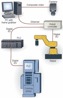
The McAlister imaging subsystem combines a monochrome CCD camera from JAI with a 25-mm lens from Pentax Imaging, a frame grabber board from Euresys, a 635-nm bandpass filter from Tectivity, and a 640-nm lighting array from Banner Engineering. The PLC is the overall master of the system, while the PC runs the imaging subsystem. Direct access to the robot always flows through the robot controller, which can be run remotely from the robot by as much as 10 meters (see Fig. 3).
AUTOMATING OPERATION
The typical work flow at a sintering plant consists of a human operator taking gears from a sintering oven, collecting them in a tray, and passing them over to a second operator, who feeds them to the press, one by one. With the McAlister system, a single operator loads between 10 and 40 parts (depending on thickness) into a “rod type nest” on the palletless carousel, and then the system takes over. The operator loading the gears need not be concerned about the orientation of the gears, although the parts must be positioned precisely to mesh with the gear tooling on the Cincinnati 200 turntables. The vision subsystem determines what that orientation is and directs the robot to make the necessary adjustments.
In the system, when a nest of stacked gears reaches the robotic loading station at the coining press, a servo ball screw raises the stack to the optimal height for collection by the robot arm. The robot collects the top gear, rotates to face the coining press, and raises the gear to the optimal height for image capture by an overhead camera. This process collects information on the gear’s center, its x/y offset from the ideal position, and the orientation of its teeth, plus data on missing features or unexpected features down to 20/1000 in.
Once the image data are captured and processed, the PC communicates with the robot controller to direct the subsequent actions of the robot. Here, a three-finger gripping tool picks up a gear, rotates it to mesh properly with the tooling in the press, lowers it, and inserts it, at which point the press goes into action, and the robot starts another cycle. Gears visually determined to be upside down are placed in a reject pan.
The cycle time for the inspection process is 3 ±0.4 s, according to Troy McAlister, company president. That’s the time expended between the point when the robot picks the gear up and the time the coining press make contact. “This would yield 20 parts per minute,” he says.
PICKING A ROBOT
McAlister’s parts-delivery system incorporates a Fanuc LR Mate 100i robot--a small-form-factor “tabletop” robot suitable for space-constrained applications with modest payload requirements. The robot provides five axes of movement or joints, labeled Joint #1 through Joint #5, beginning at its base and ending at the tip of its tool. Joint #1 (J1) provides swing so the robot can rotate (somewhat like human hips) between the carousel and the press, while J2 and J3 are the lower and upper arm, respectively, of the robot, somewhat analogous to the shoulder and elbow of a human arm.
Further up the robot, J4 and J5 coexist at the wrist, respectively, providing tilt (±120˚) and rotation (±360˚) of attached tools. The McAlister system uses a three-finger gripper, one of the three most common tools employed by minirobots, according to Fanuc Robotics’ Leipprandt. J2 and J3 are equipped with fail-safe brakes.
McAlister selected the Fanuc LR Mate 100i robot and RJ3 Mate Controller because of speed and accuracy. Its speed ranges from 240˚/s at J1 to 480˚/s at J5, and accuracy is repeatability at ±0.04 mm. The robot’s reach is 620 mm, and it can handle a load up to 5 kg (11 lb max) at the wrist. McAlister mounts the robot assembly, which weighs about 75 lb, to an 800-lb base on the factory’s concrete floor. The robot is hard-wired to its companion RJ3 controller box, using digital I/O for all communications. Both the indexed carousel and robot system can be extracted with a pallet jack.
Once Fanuc V500iA vision software is loaded on the system’s PC, the computer automatically connects to the robot controller. “We didn’t have to spend four months developing a communications protocol and writing code before teaching the robot controller about the parts,” McAlister says.
CAPTURING THE IMAGE
In one application, the robot raises a gear about 3 ft for presentation to a small JAI TM-200 camera mounted above. Based on a 1/2-in. interline CCD imager with a microlens, the camera’s frame rate is selectable 30 or 25 frames/s for NTSC and PAL video signals, respectively; and shutter speed is selectable between 1/60 and 1/10,000 s in eight increments. This camera supports selectable gain, gamma correction, and AGC. It measures 46 × 39 × 66 mm and weighs about 157 grams.
The field of interest for the McAlister system’s camera is illuminated by an array of light-emitting diodes (LEDs) from Banner Engineering. These 640-nm red LEDs, coupled with a 635-nm bandpass filter from Tectivity, provide excellent lighting for equipment on a factory floor, Troy McAlister says.
“You want to be at a different bandwidth than the plant,” he explains, “which may be standard sodium halide lighting.” Either a red or green LED/filter arrangement performs the same task-that is, filtering out most of the ambient light from the factory floor. At a distance of 12 in., the array illuminates a 4-in.-diameter area within 50% of the center intensity, according to Banner.
McAlister incorporated the TM-200 into its NEMA 12 metal housing. By placing a piece of safety glass over the area in front of the camera lens, the camera is isolated from the “oily environment” of the robot area in the system. The camera system can discern features as small as 20/1000 in., and thus, according to McAlister, the system can “run several different parts with similar features.”
The overhead camera captures a monochrome image of the gear at hand, then ships the image to a Picolo Pro 2 frame-grabber board from Euresys that resides in a PCI add-in slot in the system PC. This half-sized, low-profile PCI board captures composite video images with formats of 640 × 480 or 768 × 576 pixels at 25 or 30 frames/s. Once the image is captured, the bus-master Picolo board sends the data over the PCI bus to store in system memory. The overall time for the system to capture an image and identify the part and its orientation is less than 150 ms, McAlister reports.
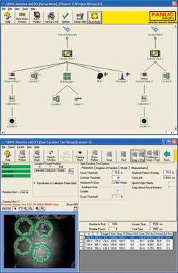
The PC runs a 2-D geometric pattern-matching algorithm in the V500iA software that compares the actual gear positioning with ideal gear positioning and determines what the robot needs to do to properly align the gear at hand (see Fig. 4). When a captured image shows that a gear has a different location or orientation than the ideal, the PC “takes that offset value and downloads it to the robot controller in matter of milliseconds,” says Leipprandt, “which shifts the program points accordingly.”
A MicroLogics 1500 from Allen Bradley is expandable to handle as many as 256 I/O points. Both it and the PC have direct connections to the robot controller: the PLC communicating using digital I/O, the PC communicating over fast Ethernet. The controller has a multiprocessing architecture with at least two resident microprocessors: one for communications, one for motion control.
The operator interface for the system resides on an Allen Bradley PanelView 550 industrial terminal, which combines a 256 × 128-pixel, monochrome (blue/gray) LCD with a 128-point touch-sensitive overlay.The LCD has a 4.75 × 2.38-in. footprint.
The PLC also communicates directly with the coining press (which has its own PLC) via digital I/O, coordinating the activity of the carousel system, robot, and press. The PLC and the PC do not communicate directly with each other, nor does the robot communicate with the press that it tends. “We only have 3 s to pick up the part and present it to the camera, shoot the picture, move the part to the press, orient its teeth, insert it into the meshing gears, open the gripper, and back out,” says McAlister. “When you’re going that fast, you don’t want to bog the robot down doing other things.”

null