Real-time vision adjusts mineral-wool quality
High-speed vision system and custom software continually monitor production under harsh conditions.
By David Lieberman, Contributing Editor
Mineral wool-also known as rock wool, stone wool, and slag wool-is an excellent thermal insulator when properly manufactured, and it has fire-resistant and audio-insulating properties, as well. The beneficial attributes of mineral wool are closely associated with its physical characteristics, which are tied to a manufacturing process that is difficult to control and even harder to monitor. FDS Research has come up with a real-time monitoring solution for mineral-wool production equipment, which, according to company president Francelj Trdic, eliminates the need for a human observer and significantly improves the quality of the final product.
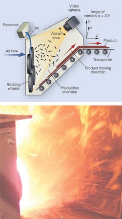
The mineral-wool manufacturing process consists of melting solid rock at approximately 1400˚C to 1600˚C, routing the resulting fluid into a reservoir, and then jetting it into a configuration of spinning wheels under the influence of gravity and an applied air flow (see Fig. 1). As a result of centrifugal forces, the high viscosity of the material, and surface tension, the molten rock forms a film around the quickly rotating wheels and then, Trdic explains, “the forces acting on this film lead to a breaking up of the film into ligaments that solidify into fibers.”
Mineral-wool fibers with a diameter between 5 and 15 µm provide the best thermal and acoustic insulation properties when they are pressed into rolls or sheets. Larger-diameter fibers are less efficient at blocking heat and noise, while smaller fibers “are considered a health hazard,” Trdic says. But worse than missized fibers are droplets of molten rock that harden into clumps when they cool, rather than forming into fibers, severely impairing the insulation properties of the final product.
Getting the process right requires continuous monitoring of key parameters, making quick decisions based on sometimes murky images, and making real-time rapid adjustments on-the-fly. FDS Research accomplishes this with an industrial PC-based vision system using its own software. The inherent variability of the parameters involved in the process over time and the complexity of their interactions mean that only adaptive regulation models are applicable for controlling the processes, says Trdic, and image analysis is “the only possible method” for determining what adjustments need to be made.
PUTTING A SYSTEM TOGETHER
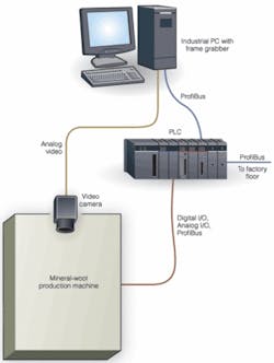
The FDS mineral-wool fabrication system is controlled by a Siemens Simatic S7-300 PLC-the CPU 319-3 PN/DP (see Fig. 2). This PLC has three ProfiBus ports. According to Siemens, the PLC implements an isochronous mode of communications to provide a deterministic response to critical signals. The PLC’s three ProfiBus interfaces are dedicated to controlling the mineral-wool production machine, along with analog and digital I/O signals; interfacing with the factory network; and communicating with the PC that serves as the brains of the machine-vision system.
The PC is a passive-backplane industrial PC from Advantech running Windows XP Professional. It contains a PCI-bus single-board computer with a 2.8-GHz Intel Pentium 4 microprocessor, Intel 845GV + ICH4 chipset with integrated graphics, 512 Kbytes of L2 cache, 533-MHz front-side bus, and 1 Gbyte of DDR SDRAM memory. This 4U-high rack-mount PC is connected to a mouse, keyboard, and 19-in. LCD monitor from Dell Computer.
The computer provides 10 PCI bus slots and two ISA bus slots. One of the PCI slots contains an intelligent 32-bit, 33/66-MHz ProfiBus master controller board, the CP5613 from Siemens, which supports data transfer rates up to 12 Mbits/s between the PC and PLC. The PC is responsible for image processing and decision making, while the PLC interfaces with the manufacturing equipment and other equipment on the production line.
Another PCI slot contains a 32-bit, 33-MHz Meteor-II/Multi-Channel frame grabber board from Matrox Imaging. It samples data at up to 30 MHz with extensive on-board buffering to prevent data loss and features real-time transfer to system or graphics memory. The board captures images over an analog video link from an XC-HR58 video camera from Sony, which FDS places within the production chamber of its system-an unfriendly operating environment. The PC and PLC are located in a far less hostile area about 50 m away.
The 50-g XC-HR58 has a compact 29 × 29 × 30-mm form factor for installation in space-constrained applications, and it can handle difficult environments such as that within the production chamber of the FDS manufacturing gear. It can endure 70 G of shock, 10 G of vibration at 20 to 200 Hz, operating temperatures between -5˚C and +40˚C, and up to 80% humidity. The XC-HR58 is part of a family of progressive-scan cameras for industrial applications. Based on a 1/2-in. progressive- scan CCD, it captures images with formats up to 767 × 580 pixels (SVGA) at rates up to 50 frames/s. The relatively large CCD enables the camera to maintain a wide field of view.
WINDOW ON THE PROCESS
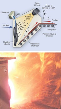
The placement of the camera is key in this installation, Trdic explains. It is mounted at the back of the production chamber in a water-cooled housing at an angle that allows it to capture the two most significant visual features of the mineral-wool production process, which are associated with fluctuations of the molten film as it hits the rotating wheels and the distribution of the film along the periphery of the wheels (see Fig. 3).
“Although a number of process parameters have a major impact on the quality of the mineral wool, it is the impingement point of the jet on the rotating wheels that is most important,” says Trdic, “and this is influenced mainly by fluctuations in the trajectory of the falling jet of molten rock.” These fluctuations are unavoidable as a consequence of complex thermodynamic and hydrodynamic processes, with temperature variations in the material, different fluid levels in the reservoir, partial clogging of the reservoir orifice, and other factors coming into play. “These parameters cannot be stabilized during the manufacturing process,” Trdic explains, “so the only recourse is to regulate the jet position so it hits the wheel at the right point for optimal fiber creation, given the current operating conditions.”
FDS overcomes these difficulties with its machine-vision software. “Algorithms were developed to detect variations in the jet trajectory with time, and this information is used to generate suitable control data,” says Trdic. The data are used by the PLC to adjust the horizontal and vertical positioning of the reservoir vis-a-vis the first spinning wheel so that the jet-to-wheel impingement point results in optimal fiber production. Other process parameters can also be dynamically adjusted based on image analysis, including air flow across the wheels and material temperature.
The complexity of mineral-wool fabrication means that, in addition to being unpredictable, the jet of molten rock is sometimes visually blocked by fibers (and/or clumps) coming off the wheels, so the machine-vision system has to rely on more than just observation. Moreover, various dynamic conditions within the jet make its shape vary over time and local eruptions occur, creating a distorted image. Random optical effects also occur. The result is that the jet trajectory may be stable over time and yet generate widely different appearances in successive frames.
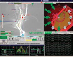
The FDS system uses knowledge of the process, recent historical data, and other factors to determine the exact characteristics of the molten jet and predict what adjustments, if any, will improve the characteristics of the mineral-wool fibers. Required adjustments are made within a 300-ms window. The GUI shows captured images of the progress of the molten rock, along with a graphical construct of it, current production parameters, and historical data (see Fig. 4).
null


