Understanding mathematical morphology
Originally developed in 1967 by Georges Matheron and Jean Serra at the Ecole des Mines de Paris, mathematical morphology is based on mathematical concepts from set theory and uses a number of operators that are useful for edge detection, noise removal, image enhancement, and image segmentation. To aid the understanding of such concepts, professor Robert Fisher and his colleagues at the School of Informatics at the University of Edinburgh have developed the Hypermedia Image Processing Reference (homepages.inf.ed.ac.uk/rbf/HIPR2/hipr_top.htm)-a set of interactive computer-based materials for image processing and machine vision. Included among them is an interactive demonstration of mathematical morphology.
The two basic operations of mathematical morphology are erosion and dilation. These operators use an input image to be eroded or dilated and a structuring element. For a binary image, white pixels represent foreground regions, while black pixels denote background pixels. For a gray-scale image, the intensity value is taken to represent height above a base plane, so that the gray-scale image represents a surface.
Structuring elements are normally smaller than the input image and in many implementations are assumed to be a particular shape, such as a 3 × 3 kernel. Binary morphology is a special case of gray-level morphology in which the input image has two gray levels of 0 and 1.
Erosion and dilation translate the structuring element over various points in the input image and examine the intersection between the translated kernel coordinates and the input image coordinates. In the case of erosion, the output coordinate set consists of those points to which the origin of the structuring element can be translated, while the element still remains entirely within the input image.
The effect of erosion on a binary image is to erode the boundaries of regions of foreground pixels (typically white pixels). Thus, areas of foreground pixels shrink in size, and holes within those areas become larger. To compute the erosion of a binary input using an image structuring element comprised of a 3 × 3 kernel, with the origin at its center, each of the foreground pixels in the input image is superimposed with the structuring element so that the origin of the structuring element coincides with the input pixel coordinates. If for every pixel in the structuring element the corresponding pixel in the image underneath is a foreground pixel, then the input pixel is left as it is. If any of the corresponding pixels in the image are background, however, the input pixel is also set to a background value.
Using a 3 × 3 structuring element, the effect of this operation is to remove any foreground pixel that is not completely surrounded by other white pixels. Such pixels must lie at the edges of white regions, and so the foreground regions shrink and holes inside a region grow.
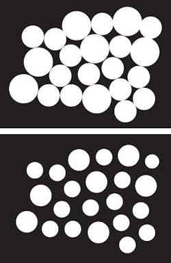
There are many special uses for erosion. One is to separate touching objects in a binary image so that they can be counted using a labeling algorithm. Figure 1 shows a number of dark disks silhouetted against a light background. The result of thresholding the image is seen on the right.
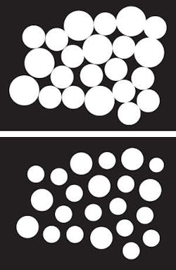
To count coins in an image is not easy since the touching coins form a single fused region of white, and a counting algorithm would have to segment this region into separate coins before counting. By eroding the image twice using a disk shaped structuring element eleven pixels in diameter, all the coins have been separated neatly and the original shape of the coins has been largely preserved. At this stage a labeling algorithm can be used to count the coins. The relative sizes of the coins can be used to distinguish the various types by, for example, measuring the area of each distinct region.
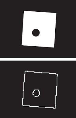
Dilation is the dual of erosion. Dilating foreground pixels is equivalent to eroding the background pixels. Dilation can be used for edge detection by taking the dilated image and subtracting the original image, thus highlighting those new pixels at the edges of objects that were added by the dilation. Figure 2 shows a square image with a hole in its center. By first dilating the image using a 3 × 3 square structuring element and subtracting the original image, the edges of the image appear.
To visualize the effects of erosion and dilation on images, the Biomedical Imaging Group at EPFL has developed an on-line demonstration that shows the basic operators of mathematic morphology using a 3 x 3 structuring element (bigwww.epfl.ch/demo/jmorpho/index.html). Using the demo, you can upload images and perform both erosion and dilation operations.
Virtually all other mathematical morphology operators can be defined in terms of combinations of erosion and dilation along with set operators such as intersection and union. Some of the more important are opening, closing, and skeletonization. These are more fully described in Fundamentals of Image Processing, an on-line reference from the Quantitative Imaging Group at Delft University of Technology.
Because these operators lend themselves to the pipelined nature of FPGAs, Damien Baumann and Jacques Tinembart at the Ecole d’Ingenieurs de Geneve have built a VHDL morphological library with Matlab to implement morphological algorithms without writing a line of VHDL code (see cui.unige.ch/spc/Presentation/2004/baumann_3_12_04.pdf. Using BTMorph, the software can generate VHDL code from a morphological script and create a configuration file that can be loaded into an FPGA using Matlab.
null


