Strobe light helps freeze solder balls
By C. G. Masi,Contributing Editor
Electronics manufacturers pack remarkable functions into their products by using advanced surface-mount-technology packaging for installing integrated circuits (ICs) on boards. Perhaps the most advanced packages are ball-grid arrays (BGAs). They are generally large, flat plastic packages (a few centimeters on a side) containing silicon ICs that are small (tens of millimeters on a side). Electrical connections between the ICs and the circuit board that deliver power and signals are typically made through hundreds of tiny spheres of eutectic alloy (that is, solder) attached to the IC connections under the package—thus the origin of the term ball-grid array.
Microspheres (solder balls) for different package styles range from 80 to 800 µm in diameter. All, however, have to be manufactured to exacting tolerances because solder-ball volume is an important parameter for solder-joint quality. Too much solder per connection promotes solder bridges and short circuits. Too little solder results in opens or weak connections that fail in the field.
A typical advanced consumer-electronics product, such as a personal computer, might contain one or more BGA-packaged ICs. These packages are manufactured in unit volumes reaching into the hundreds of thousands per year. Hundreds of balls per package times several packages per unit times hundreds of thousands of units per year adds up to a huge demand for precision alloy microspheres.
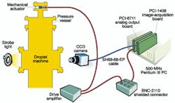
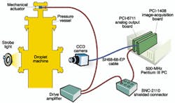
PROCESS PROBLEMRecently, a microsphere producer called on system-integrator Bloomy Controls (Windsor, CT) to help improve the yield of its microsphere-production process using vision and imaging technology. Several production problems existed with the conventional measurement system, but leading the list was poor yield—25% to 30%. Another serious problem concerned the control software. Written in C, the software proved inadequate and poorly documented. Production engineers could not understand what the system was doing, why it worked so deficiently, and how to improve it.The machine for manufacturing microspheres consists of a pressure vessel, approximately 15 ft tall, containing an inert gas, such as nitrogen or argon, at above-atmospheric pressure (see Fig. 1). A small crucible in a housing at the top of this pressure vessel contains molten alloy from which the microspheres are made. A vibrating plunger, driven by a piezoelectric actuator, forces this molten alloy through a precision ceramic aperture. The higher the frequency of the piezoelectric drive signal, the smaller the spheres become during production. Conversely, driving at a lower frequency produces larger spheres. This approach is known as uniform droplet spray (UDS).
Two ports in the pressure vessel located opposite each other at about 6 in. (15 cm) below the ceramic nozzle provide access for a machine-vision system to monitor droplet size and quality. One port is used by a strobe light to backlight the microspheres as they free-fall between the ports. The other port is used by a CCD camera with a macrolens that captures and delivers images to a supervisory PC.
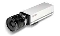
The strobe-lamp xenon bulb sits at the focus of a 4-in. (100-mm) parabolic reflector. The formed beam passes through a multiprismatic diffuser plate to backlight the spheres. The camera is a Pulnix America Inc. (Sunnyvale, CA) TMC-7DSP 1/2-in. interline-transfer CCD camera (see Fig. 2). It provides 768 x 494- or 752 x 582-pixel resolution using 8.4 x 9.8- or 8.6 x 8.3-µm pixels. The macrolens provides an approximate 150-mm working distance and forms its image on the 6.4 x 4.8-mm imager sensor with an approximate 2-mm field of view. Generally, during operation, one or two microspheres appear in each frame at any one time.
The supervisory computer analyzes the captured images and automatically extracts information about the microsphere(s) in each frame. The key piece of information desired is the spheres' diameters. If the diameters are trending out of tolerance, the computer can adjust the actuator-drive frequency to bring the diameters back into specification.
Another problem uncovered by Bloomy Control was random outliers. The UDS production process makes spheres that reside within a plotted diameter distribution curve that has a significant natural width. However, a few percent of spheres fall within the wings of the distribution curve and are therefore out of tolerance. "If we accepted all of the outlying data that we were looking at," recalls Robert Hamburger, principal engineer at Bloomy Controls, "we would end up with a noisy control loop that would not stabilize within a reasonable amount of time."
The outlier problem was quickly solved. Rather than using a tight feedback loop that reacted immediately, the engineers used the incoming data to build a picture of the diameter distribution. They wrote an algorithm that rejected events that were more than about 15% outside of tolerance. They used the remaining events to build a running average to track the distribution's mean value.
CLEAN SLATETo correct the existing problem-riddled software system coded in C, the Bloomy Control engineers decided to go with a clean set of algorithms and recoded the entire software system from scratch. They used the LabVIEW graphical programming environment from National Instruments (Austin, TX). They selected LabVIEW because it produced open source code, which was easy to identify and understand, modular, and properly documented.The new software acquires an image of one or more spheres that are illuminated by the strobe and captured by the camera. It determines how many spheres are being imaged and measures their diameters. The diameters are compared to the desired (set point) diameter for the process, and a correction signal is generated if necessary. This correction signal adjusts the drive frequency for the piezoelectric actuator, providing closed-loop control over the size of the spheres that the UDS process makes.
While the system is running, it also collects statistics on how many spheres are recognized and the average diameter of those spheres. Other computed statistical data involve a standard-deviation measurement that provides information about the quality of a manufacturing run. The vision system can accept a large number of adjustable parameters in an effort to optimize control over the solder-ball fab system. The operator also can change the set point and various closed-loop control parameters that affect system calibration. These capabilities allow the microsphere manufacturer to custom tailor the system controls for different product sizes and, potentially, for different eutectic alloys.
The microsphere-manufacturing application runs on a Dell Computer (Austin, TX) desktop computer with a 500-MHz Pentium III processor. The computer also contains two peripheral boards associated with the application. A National Instruments (NI) PCI 1408 image-acquisition board captures images, and a NI PCI 6711 analog output board generates a sine wave of varying frequency to control (after suitable amplification) the piezoelectric actuator.
How the drive frequency, which is between 1 and 2 kHz, translates into sphere-size control depends on other process factors, such as the spray apparatus' nozzle size, temperature of the metal alloy, and gas pressure in the pressure vessel. The particular drive frequency selected for system control is the one most amenable to rapid, accurate, electronic adjustment.
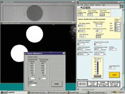
An eight-bit monochrome image comes from the camera as standard RS-170 video. Then, the PCI 1408 image-acquisition board digitizes the analog image from the camera. After the image is delivered to the computer, the system software chooses an image from the digitizer and performs a thresholding operation to convert the gray-scale image into a binary image. The spheres' projections on the image plane are shown as white circles on a uniform black background (see Fig. 3).
The image then enters a LabVIEW IMAQ routine called "IMAQ Circles," which forms the core of the sphere recognition and measurement system. It looks for circular objects and can distinguish among multiple circular objects in an image, even if they are overlapping. It returns a cluster of information for each circle such as location, eccentricity, and pixel size.
The Bloomy Control software processes this circle information in two different ways. It rejects all circles that are grossly out of tolerance—those being more than 15% above or below the running average. The remaining information goes into updating the continuous running average. The running average feeds into a closed-loop proportional-integral-derivative control algorithm, which generates the correction signal for the actuator drive.
The vision system acquires and processes about 10 images per second. Image acquisition can run at a standard video rate, but is limited by the amount of processing that needs to be done to recognize the spheres and measure their diameters.
System calibration between the pixel space of the image-acquisition system and NIST-traceable measurements in physical space is necessary to obtain accurate results. The manufacturer had already solved this problem by obtaining an optical-system calibration target from Edmund Industrial Optics (Barrington, NJ).
To calibrate the vision system, the engineers place the circular calibration target in the camera's focal plane and illuminate it. The imaging system measures the target's image in terms of pixels, and a utility algorithm built into the software system determines the pixel-to-micron conversion ratio. Once calibrated, and assuming that other system geometric factors don't change and the camera doesn't move, the calibration stays fixed for long periods of time. "The system that we put in place," Hamburger reports, "dramatically increased the in-tolerance yield, as well as the overall number of spheres that we could recognize and measure, and for which we could gather statistics." For a typical 20-min run, the new vision system collects data on more than ten times the number of spheres than the previous system could.
COMPANY INFORMATIONBloomy Controls Inc.Windsor, CT 06095Web: www.bloomy.comDell Computer
Austin, TX 78714
Web: www.dell.com
Edmund Industrial Optics Inc.
Barrington, NJ 08007
Web: www.edsci.com
National Instruments
Austin, TX 78759
Web: www.ni.com
Pulnix America Inc.
Sunnyvale, CA 94089
Web: www.pulnix.com


