Data standards ease vision-tester integration
By C. G. Masi,Contributing Editor
Standards have steadily gained ground in the systems-integration activities of machine-vision applications. In the past, vision and imaging vendors mainly offered proprietary products to protect their market share, but this approach made it difficult for integrators and end users to build multivendor systems.
The major problem is that no one company can be the best with all the diverse technologies needed to construct today's machine-vision systems. For example, a company might be a leading supplier of cameras but have less expertise in image-processing technology. In the nonstandard world, system integrators are forced into trade-offs—accepting less than the best performance in one technical area to obtain the best in another.
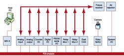
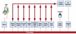
FIGURE 1. Test system designed by VI Engineering for checking personal-watercraft control modules consists of a computer, a PXI chassis containing several instrument modules, ancillary power supplies, and a fixturing device that mates with the control module under test. The machine-vision system, which performs the first test sequence—inspecting the fuse block before system power is applied—sends S-Video signals to a frame grabber installed in the PXI chassis. From there, the captured image goes to the host computer over a MXIbus link. This test system is built around a VI universal test system product, which uses highly adaptable standard modular instrumentation devices to accommodate a variety of applications.
Incorporating interface standards makes the system integrator's job much easier. Without the skillful use of standards, designing and building a complex vision-electronic-computer test system is a monumental task. In practice, system integrators are forcing more and more equipment vendors to adopt standards.
Expertise in the use of a variety of standard interfaces is a must for vision-system integrators. In fact, many system integrators, such as VI Engineering (Indianapolis, IN), have boosted their business by efficiently using interface standards. These integrators provide systems featuring tight integration, premium components, and enhanced flexibility to handle new tasks.
For example, a North American manufacturer of in-vehicle electronic products chose VI Engineering to develop a system to functionally test control modules it is building for a personal-watercraft manufacturer. The watercraft uses the controller-area-network (CAN) standard to bus signals in and out of a central control module. This module receives information from sensors scattered around the watercraft and uses those inputs to ensure that the watercraft is performing according to the operator's commands. It then sends control signals out over the CAN bus to actuators that put these command decisions into effect. The bus also handles direct analog and digital inputs and outputs, such as dashboard switch-position signals and display outputs.
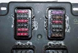
The functional test system needed a machine-vision system to verify the correct installation of the watercraft's fuse block by reading the fuse color codes and printed alphanumeric identifiers. The fuse block is built into the control module. The test system makes a functional test by providing direct and simulated inputs via the CAN bus and observes the control signals the module generates in response.
Of course, the fuses must be installed correctly before the functional test is conducted. Missing or wrong installed fuses would negate the value of all the electrical tests conducted by producing spurious rejections, module damage, and wasted test time. If the fuse verification were not done first, good modules with wrong fuses would be rejected. They would then have to be retested after the fault was corrected.
It is more cost-effective to begin a test session with an automated visual inspection of the fuse block to verify fuse placement and abort the electrical tests for any fuse blocks that fail the inspection. The tester can shunt those modules off to a repair station, where a technician can correct the problem and return the modules to the tester input stream. In that way, the tester performs the lengthy electrical test program only on modules that have no, or easily remedied, flaws.
TEST-SYSTEM ARCHITECTURESundaram Raghuraman, VI Engineering team leader, based the test-system design on his company's existing Universal Test System (UTS). The UTS is a generic functional test system that can be easily customized. Built around PXI (PCI eXtensions for Instrumentation) and MXI (Multisystem eXtension Interface) modular-instrumentation standards, the UTS can be customized by adding or deleting standard commercial-off-the-shelf modules available from a variety of vendors, and similarly, by modifing the control software driving the test system.The fuse-block test-system architecture consists of two stacks of equipment (see Fig. 1). Standard construction practice for automatic test equipment (ATE) calls for a fixture receiver that mechanically accepts another fixture into which the unit under test (UUT) is plugged. This practice allows the ATE to test different UUTs with minimum modification.
As control modules come off the production line, ATE operators plug them individually into the test fixture for testing. As a result, the test fixture wears out faster than any other part of the test system. Having a separate, easily removable component makes the test fixture easy to replace.
The frame-grabber electronics are built into a PXI module installed in the PXI chassis. Under control of a host computer from Dell Computer Corp. (Austin, TX), the frame grabber captures an image of the fuse block and ships it to the host computer over an MXI-3 link. The MXI standard was developed in the late 1980s to help ATE builders connect desktop computers to host systems built to the VXI (VME eXtensions for Instrumentation) standard.
SOFTWARE ARCHITECTUREIn standard ATE practice, a test program set (TPS) includes the test fixture and the software needed to test a particular UUT. For the control-module test system, the TPS includes an associated fixture and a test program that the VI Engineering team wrote using TestStand, an ATE-specific programming environment from National Instruments (NI; Austin, TX). The individual tests called by TestStand were developed using NI LabVIEW software.The VI engineers wrote the vision-application portion of the TPS using NI IMAQ Vision software. The TPS consists of code modules called test sequences that embody different tests that the ATE must perform on each control module. The test sequences direct the ATE hardware components to source the necessary signals and acquire the UUT's responses. Then they analyze those responses to determine whether the UUT passes that particular test. Based on the test results, the test program decides whether to continue testing or flag the UUT for off-line repair. The test sequence is also capable of recommending a particular remedy for a failed UUT.
The fuse-box inspection represents a test sequence. The system software first picks out the registration features in the UUT image and then compares the image to a template. The test system uses a GP-KR222 NTSC color video camera from Panasonic Security & Digital Imaging Co. (Secaucus, NJ). This NTSC-based CCD camera provides 768 x 494-pixel resolution, 30-frame/s rate, 480 TV lines, 50-dB signal-to-noise ratio, and a minimum illumination of 2 lux at f/1.2. A manual zoom video lens from Edmund Industrial Optics (Barrington, NJ) helps the camera and ATE verify that each fuse is properly installed in the right place with the correct orientation and has the correct numerical value (see Fig. 2).
Fuses for the control module are marked with color codes and alphanumeric identifiers. A 10-amp fuse, for example, would be a certain color and have a "10" mark. The vision system converts the RGB (red-green-blue) signal into an HSL (hue-saturation-luminance) signal. The HSL format makes it easier for the computer to verify that the color (hue) of a fuse is within specification, while separating out the luminance information, which is highly susceptible to lighting-condition vagaries.
Seeing and reading the alphanumeric printing verifies that the fuse is installed correctly and confirms the color-code information about the fuse value. If the control module under test passes all the inspections, then the test sequence passes it. The test program then starts the electrical tests.
If the vision test sequence finds a problem with a particular control module, it stops the test, signals the technician, and recommends a remedy. Typical faults include a fuse installed backwards, wrong fuse value, or missing fuse. These typical mistakes are usually made by pick-and-place automatic assembly machines. A less often mistake is not properly fitting a correct fuse into its socket.
Correcting these faults is something the technician can do while the ATE tests the next module. After fixing the problem in the failed UUT, the operator can return the module to the test system's input stream.
Automated handling equipment is still not as flexible as is a human operator. When the vision system flags a module for repair, the automated handler merely shunts it off to a defective bin. A technician then makes the fix that the ATE recommends.
Company InformationDell Computer Corp.Round Rock, TX 78682Web: www.dell.comEdmund Industrial Optics
Barrington, NJ 08007
Web: www.edmundoptics.com
National Instruments
Austin, TX 78759
Web: www.ni.com
Panasonic Security & Digital Imaging Co.
Secaucus, NJ 07094
Web: www.panasonic.com
VI Engineering Inc.
Indianapolis, IN 46256
Web: www.viengineering.com


