Web vision system finds film defects
By C. G. Masi,Contributing Editor
High-speed production webs were among the first successful applications for automated optical inspection (AOI) using vision systems. The success of automated inspection was not based on the ease and reliability of vision-system development for web applications but on the near impossibility of thoroughly inspecting webs in any other way. Web manufacturing techniques are used to produce rolls of material in thin, flexible sheet form. Fabrics, paper goods, plastic films, and other flat products are manufactured using these techniques.
Webs typically move at blinding speed—much too fast for human inspectors to follow. Therefore, before automated inspection methods were developed, web-manufactured products were inspected on a batch basis. In a newspaper press, for example, the web was set up and run at relatively low speed until a few pages had been printed. Then a human inspector checked the print quality of those few examples. If the pages were judged acceptable, the web was accelerated up to its maximum print rate. This manual inspection method assumed that the subsequent pages would be printed with the same quality.
Manufacturing faults that arose during high-speed web operations generally affected entire lots of material, all of which would have to be discarded at the end of the process. Even worse were transient faults, such as contaminants dropping onto the web; these flaws would sometimes go undetected until the customer tried to use the product.
This background information was well known to the engineers at Materials Science Corp. (MSC; San Diego, CA) as they developed a production web system to manufacture metallized plastic film that is used to block excess solar radiation in a variety of applications. Because this film is intended for people to look through, any manufacturing defects, such as gels, contaminants, or coating problems, are unacceptable. The film materials are intended as a coating for glass, so they must be as defect free as the glass.
Unlike other web-manufactured materials, the shipped film products had to be defect-free; that is, the web had to be 100% inspected in real time. After exploring all of the available alternatives, MSC contracted Wintriss Engineering Corp. (San Diego, CA) to build an AOI system that could perform the 100% film inspection in real time at full web speed.
"We went through a thorough process to demonstrate the ability to detect the film defects," recalls Robin Becker, senior vice president at Wintriss. "First, we analyzed samples of their product on our laboratory system to establish the proper inspection criteria. Then we installed a single-camera demonstration system on the manufacturing line. During the first phase of operation of the demonstration system, we detected coating defects that were not readily visible."
MSC needed 100% in-line inspection of films at three different production stages: lamination, hard coating, and adhesive application. During these production runs, the films had to be inspected to detect, classify, display, and record various defects, including hardcoat scratches, gels, and contaminants. Additional vision system requirements included single-line installation with no restriction placed on roll length; accommodation of 60- to 72-in.-wide film; maximum travel speed of 150 ft/min; identification of embedded and surface defects (both sides of film) including dry spots, inclusions, die streaks, scratches, creases, and coating streaks; 24/7 operation; and an algorithm for automated product changeover based on transmission characteristics of the new material with no user input required.
Vision platform
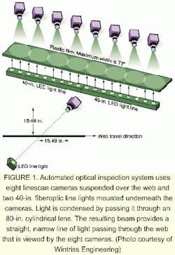
Based on the Wintriss Web Ranger 1000 product line, the developed AOI system uses eight OPSIS 5150 cameras connected over an Ethernet-to-PC link (see Fig. 1). This link provides an operator interface and allows complete control of all web-inspection functions. The system can be connected to an existing network for remote access and for printing reports.
The cameras are supported on a frame positioned above two 40-in.-long (1-m) fiberoptic light lines placed end-to-end to form an 80-in.-long (2-m) light line. The light is collimated using an 80-in.-long (2-m) plastic rod lens. This light source produces a brightness of up to 80,000 lux.
The system is able to detect all defects that have a defect-to-good material contrast greater than 15%. It also sees contaminant particles larger than 20 mils (0.5 mm) in diameter and hardcoat scratches larger than 4 mils (0.1 mm) in width and 100 mils (2.5 mm) in height. Other detected defects include dry spots, inclusions, die streaks, creases, and coating streaks.
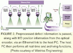
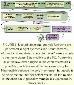
The cameras contain an on-board processing capability configured by a field-programmable gate array (FPGA) that handles image processing and a Motorola PowerPC microprocessor for image analysis and camera control. The on-board processing enables the cameras to analyze acquired images and then communicate only the defect-associated information over an Ethernet link (see Fig. 2). In addition to information associated with the defects, the cameras provide the time when the detection occurred, defect classification, location in the cross-web (CD) and longitudinal (MD) dimensions, size information, and a defect image. These data are passed via an industrial standard 100Base-Tx format to the system-host Ethernet cards.
The cameras are locked to the web motion using an optical encoder attached to a rotating idler. The encoder delivers a pulse synchronized to the web's movements. This feature allows the AOI system to hunt for repetitive defects that may be associated with one or more of the rollers. When it detects such a repetition, it uses the repetition period to identify one or more of the rollers as suspect, making problem identification and repair more efficient.
Each of the eight OPSIS 5150 linescan cameras supplies six digital outputs and four digital inputs. The vision-processing software runs the high-contrast defect-detection pipeline on the camera (see Fig. 3). It also tracks the edge of the web and controls the digital inputs and outputs and two digital-to-analog (D/A) channels on each camera. The digital inputs are used for accepting user-defined signals such as cut signal and job-change signal. The digital outputs are used to turn on alarms and mark the web. The D/A channels are available for process control.
The VxWorks real-time operating system running on the cameras controls the digital outputs. This setup ensures precise control of digital output transitions, which, in turn, allows the system to electronically mark the web with high accuracy based on either encoder count or timer delays.
The host computer is a 500-MHz Pentium III running Windows NT. It operates with a 56.6-kbit modem, Ethernet cards, 256 Mbytes of RAM, a 17-in. monitor, and a read/write CD drive. Other system peripherals include a tricolor visual alarm, an audible alarm, a camera power supply, an input/output (I/O) junction box with Opto-22 digital inputs and outputs, and a color inkjet printer.
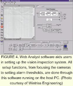
The system runs with two major software applications residing on the host PC. The Web Analyst software enables web setup, including the designation and classification of defects. The Web Inspector software provides online monitoring and data analysis, including defect viewing, process mapping, data archiving, and statistical data.
The Web Analyst software enables user-defined information to be entered for controlling the cameras and the Web Inspector software (see Fig. 4). It offers tools for setting up the parameters needed for inspection. These include a line-profile tool to focus and align each camera, a histogram tool to designate thresholds, a high-resolution image-capture-and-load tool, a threshold tool to set minimum and maximum intensity ranges for defects and to display the detected defects in color, and a blob-analysis tool to verify and test classification setups.
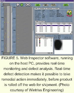
The Web Inspector software is a Windows NT-based, process-monitoring tool that allows users to view defects and other inspection-related data in real time (see Fig. 5). The PC receives inspection data from the cameras via the Ethernet interface. It seamlessly integrates the data from multiple cameras to generate displays for operator viewing and also archives the results in a SQL (Structured Query Language) or Access database. The graphical user interface displays a web map, which provides a background image of the entire web, a list of defects, an image of the current defect, the dimensions of the defects, and system status information. In addition to these display and archive tasks, the PC also can perform trend analyses on the different defect types and report their frequency and position.
A unified two-dimensional web image, created by integrating the images from multiple cameras, can be displayed on the monitor. This allows users to visually check the fidelity of the images from all the cameras. Users can pan and zoom within the web image, which is updated every 30 s.
The Web Inspector provides a high-resolution video image of a detected defect as soon as the defect is detected. This image is stored in the database and also is displayed on the host monitor. Using this image, the operator can recognize the defect, identify the cause, and take corrective action.
Since defect images are stored in the database, they also can be analyzed off-line using the Web Analyst. This analysis is useful for tuning the defect parameters. For example, if the system erroneously classifies a good product as containing a defect, the operator can view the defect image and then change the defect parameters to suppress further false detections.
The software tracks the position and characteristics of the detected defects. Alarms can be generated if statistical analysis determines that the defects indicate a trend. Defect-trend-analysis graphs provide users with the necessary information to identify potential process problems. Then, users can retrieve archived data based on date, time, or roll number.
The reporting feature allows users to generate, print, and view two reports while an inspection is in progress — automatic reports and manual reports. Automatic reports, including job, d-off, roll, and shift, are generated without human intervention at the end of the corresponding operation. Manual reports can be time-based, such as a summary of web inspection data for the last four hours.
The SQL database is a warehouse of all the inspection-related data. It allows the storage of all relevant information and provides access to historical data based on SQL queries. Custom reports can be generated using third-party report-writing tools.
For the initial demonstration of the AOI system, Wintriss set up a single-camera Web Ranger at MSC Specialty Films. The web line speed ranged from 80 to 100 ft/min (0.4 to 0.5 m/s). The CD resolution of this demonstration was 2.2 mils (0.056 mm) per pixel. The camera was operated in exposure mode running at a constant speed of 3000 lines/s. At a speed of 80 ft/min., the MD resolution was 5.3 mils/line; at a speed of 100 ft/min. (0.5 m/s), the MD resolution was 6.6 mils/line (0.17 mm/line).
The demonstration used specially prepared defective material to test the system's ability to find particular defects of interest and perform alarm and reporting functions. It was so successful that MSC purchased and installed the complete multicamera system.
COMPANY INFORMATIONMaterial Sciences Corp.San Diego, CA 92121Web: www.matsci.comRodenstock Precision Optics Inc.
Rockford, IL 61109
Web: www.rodenstockoptics.com
Wintriss Engineering Corp.
San Diego, CA 92121
Web: www.weco.com
