High-speed cameras target process monitoring applications
Fast frame rate cameras are being used in industrial applications to troubleshoot machinery on high-speed production lines.
Nathan Cohen
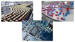
In many machine vision applications, cameras, lighting, computers, and networking systems are used to inspect products as they are manufactured. Canned food, bottles, engine parts, and electronic sub-assemblies, for example, may be checked for correct label orientation, fill levels, barcodes, and the presence/absence of components (Figure 1).
To produce such products at high rates, sophisticated mechanical conveyors and reject mechanisms must drive these products along the production line at high-speed. Because these products are made so rapidly, any breakdown or malfunction in this equipment results in the line being halted, repaired, and re-started, resulting in expensive downtime costs. If any faults relating to breakdowns are isolated right away, the manufacturer can repair the breakdown faster and reduce the downtime cost. To isolate these faults, manufacturers use high-speed vision systems to inspect features of the products and to monitor the conveyors and reject mechanisms being used.
Integrated systems
Several companies today produce integrated systems to perform such tasks. As with every aspect of implementing machine vision systems, the task of choosing which system to use is highly application specific. The speed of the production line or process being monitored dictates the types of machine vision cameras, camera interfaces, triggering mechanisms, host computers (or “event recorders”), and lighting that must be deployed in the system.
Perhaps more importantly, should a fault occur, the system’s user interface must allow an operator to isolate rapidly the cause of the fault and report it to the relevant shop-floor personnel.
In a typical monitoring system, a camera or series of cameras are interfaced to an event recorder to capture a sequence of high-speed images that can be analyzed to diagnose the cause of any mechanical equipment failure (Figure 2).In such configurations once the system has been triggered, either from the camera or though the event recorder, images are then stored for a pre-set time for later playback and analysis. In monitoring such high-speed events, systems can be triggered in a few different ways. Should a high-speed bottling line fail for any reason, the number of bottles passing along the production line will be reduced.
Sensing the system
Such events are often detected using different sensor types, perhaps the most common of which is the photoelectric sensor. These sensors detect a change in light intensity between the emitted and received light source from the sensor. Available from companies such as Pepperl+Fuchs (Mannheim, Germany; www.pepperl-fuchs.com), these sensors can also be used to count the number of bottles passing along the production line since the sensors will detect a series of pulses that can be measured. Should the period between pulses alter dramatically, the sensor can then be programmed to output a PNP/NPN signal to trigger a camera or computer.
Numerous types of these sensors exist, ranging from through-beam sensors, retro-reflective sensors, diffuse mode, and color sensors, all of which can be used to detect any spurious events that may occur on high-speed production lines. When such machinery fails, for example, the level of vibration of the equipment may increase. Thus, vibration analysis systems can be used to determine the condition of the production equipment.
By monitoring the vibration levels using sensors that measure the displacement, velocity, and acceleration of the equipment, and comparing the output of such sensors with a range of expected values, an output can be derived to trigger the camera or computer. Companies such as Hansford Sensors (Inman, SC, USA; www.hansfordsensors.com) manufacture sensors for this purpose.
While photoelectric, vibration, and acoustic sensors can all be used to trigger an image capture sequence, so too can information from the camera. This can be accomplished by analyzing the captured images using relatively simple algorithms and triggering the system should any change occur. For example, the grey-scale value of the image could be analyzed and compared with a range of known reference values. Alternatively, pixel-to-pixel differences between incoming images could be compared with a reference image, and should these differences fall outside a specified range, the system would trigger a recorded image sequence.
Reducing latency
In developing such systems, it is vitally important for the system’s integrator to realize that, whatever sensor or camera is chosen, there will be some latency between the time that the sensor or camera detects the event and the time taken to start the image recording sequence. This may range from a number of microseconds to a few milliseconds, depending on whether the image sequence is triggered using the I/O trigger on the camera or that on the event recorder.
To reduce this latency, many systems use the camera I/O, as when using an event recorder or a programmable logic controller (PLC), latency will be longer due to the time required to poll the interrupts and generate a trigger signal to the camera. Here, minimum latency is determined by the time needed to poll the input via software and generate a trigger to the camera to start an imaging sequence.
Similarly, detecting and analyzing captured images using the camera itself or using software running on the event recorder or PLC will also add latency, since this will involve image capture, image analysis, and then generating an output signal. For this reason, triggering the system using a camera tends to be more complex and has a higher system latency.
Choosing a camera
Just as how to trigger the camera plays an important role in the design of such systems, the choice of which camera to use is equally important. Cameras designed for high-speed imaging tend to be very application specific. For applications such as ballistics and automobile crash testing, for example, even the fastest of camera interfaces cannot be used to capture image sequences with 1024 x 1024-based CMOS sensors.
For this reason, camera companies such as Vision Research (Wayne, NJ, USA; www.phantomhighspeed.com) and Photron (San Diego, CA, USA; www.photron.com) have developed cameras such as the Phantom V2512 and Fastcam SA-Z that allow 1280 x 800 x 12-bit pixels and 1024 x 1024 x 12-bit image data to be captured at speeds of up to 10,000 fps and 25,000 fps respectively. This results in hundreds of Gigabits of data that need to be captured by the camera.
To capture these images, such cameras must be designed with Gigabytes of on-board memory so that image sequences can be captured, stored, and then transferred over high-speed interfaces for later analysis by motion analysis software. Such interfaces generally tend to be based on the GigE or 10GigE standard.
Several reasons exist for this being the interface of choice for such high-speed cameras. First, the GigE interface is extendable and currently ranges from GigE, 10GigE, 40GigE, and 100GigE. Secondly, unlike standards such as CoaXPress (CXP) that will also support high bandwidths of up to 100Gbits/s, no expensive PC-based frame grabber is required to interface the camera to the computer, lowering system cost. Furthermore, although the maximum cable length of the CXP-based standard is approximately 70 m, GigE-based implementations can use cables that extend the camera to computer interface to 100 m.
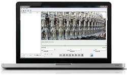
By leveraging the power of GigE Vision, camera vendors are now introducing low-cost, high-speed cameras that do not require on-board camera memory to store image data. While such cameras still cannot be used in very high-speed applications, they are now being deployed in less-demanding factory process monitoring applications.The Imperx (Boca Raton, FL, USA; www.imperx.com) B0620, a 640 x 480 CCD-based GigE camera with Power over Ethernet (PoE), for example, can be interfaced with the company’s Ethernet/IP Process Video Recorder (EIPVR) event recording system to record up to 60 seconds of video at 250 fps, or longer at slower frame rates. In operation, the system automatically saves the images to the recording system, and using the company’s recording and playback software can be used to view the recorded events at a user-configurable playback speed (Figure 3). Thus, the system can be deployed to eliminate line stoppages and troubleshoot mechanical equipment integration without the need for an expensive, dedicated high-speed camera or a costlier CoaXPress-based solution.
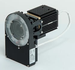
To capture images at rates of 250 fps and eliminate blurred images, strobed LED lighting is often used. Here, the firing of the strobe must be properly synchronized with the exposure time of the camera. To ensure that this is the case, manufacturers offer dedicated strobe lights. Imperx, for example, offers is LED PoE ring light to simplify such LED installations. In the design, ring light power is derived from a PoE interface and can be directly triggered from the camera (Figure 4).


