Improve your vision system with computational imaging
Paul Downey and Marc Landman
Used increasingly in machine vision for improving the capability of a camera and to reveal image data not previously possible, computational imaging (CI) works by capturing a series of input images under different lighting or optical conditions. Application-specific image processing merges those images together, resulting in an output image containing the most pertinent details to specific machine vision tasks.
Though already in widespread use within digital photography, advances in technology and the latest high-speed cameras make CI techniques viable for many machine vision applications. CI permits the creation of better or previously impossible images, shortens development time, and with its targeted feature extraction, directly outputs optimal images for vision algorithms.
Since CI works on stationary or moving parts and produces more useful images than a single image capture with fixed lighting and optics, it can be applied to a variety of machine vision applications. There are numerous examples of CI techniques that can be leveraged to improve industrial vision systems, including increased contrast, higher-resolution color, multispectral features, extended depth of field, segmented 3D information, and combinational illumination. With CI, system designers can start to think in new ways about creating solutions to difficult imaging problems and generate higher quality images at lower cost.
A closer look at how CI works
Image capture is fundamentally the same today as it was forty years ago: a single exposure taken with fixed optics and lighting. For more complex imaging challenges, typical solutions for achieving better images involve using different lighting and lensing or to fix the problem of poor image quality in software. Both approaches add extra time and cost to imaging solutions and still often fall short in producing optimal images.
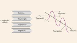
With CI, programmable lighting and lens control systems typically combine to create image capture sequences that vary application-specific parameters such as illumination direction or angle, wavelength, intensity, polarization, or focus (Figure 1). With image processing software, these images are then combined into a single image of enhanced quality that extracts the features needed for an inspection task. Existing CI tools enhance contrast, provide ultra-resolution color, extend depth of field, extract 3D surface information, remove glare, combine well-known lighting techniques, and leverage multispectral information in a single image.
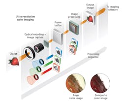
Figure 2 shows the practical elements comprising the key steps of CI, which can be generalized as computational illumination/optical encoding, image capture, and image processing/decoding. Using a monochrome camera with a full-color ring light with three-channel control of RGB output, full resolution RGB color images can be acquired at practical data rates. By grabbing a sequence of three monochrome images correlated to R, G, and B strobes, a full color composite image at the full monochrome resolution can be created by aligning the images and using the R, G, and B values for each pixel to create the color pixel.
Advantages of composite images
Figure 2 shows much sharper composite color images than that of a single image capture with a Bayer or mosaic color camera. The images are similar to those from 3-chip cameras without the expense, special prism, or lens limitations, and at much higher resolutions. The advantage of CI is the ability to have complete color information at the full pixel resolution of the imager. Due to the spatial effects of interpolation, common Bayer imagers capture color information, but lose spatial resolution across several pixels. Additional benefits to a color composite imaging solution include cost savings and flexibility. The cost of a composite color imaging solution using a full color light and monochrome camera can be much less than using a 3-chip camera and white light, plus one monochrome camera can be used for both high resolution greyscale and color imaging.
Let’s look at some common computational imaging methods used in machine vision:
Photometric stereo separates the shape of an object from its 2D texture or surface coloring. Typically, this technique highlights 3D surface features or imperfections in one image (shape image), and removes glare from highly-reflective parts (texture image).
High dynamic range (HDR) imaging is a light-based method for creating images with higher contrast ratios and less noise.
Ultra-resolution color uses RGB lighting and a monochrome image sensor to create higher resolution color images with no interpolation artifacts.
Extended depth of field (EDOF) extends the depth of field of an imaging system without losing light or reducing magnification. It works by merging a set of images taken at different focal planes.
Bright field/dark field combines the advantages of two well-known, but opposite lighting techniques to reveal features created by both methods in a single image.
Multispectral imaging enhances images with maximum contrast from multiple spectral bands. Typically, this method combines the features seen in the ultraviolet (UV), visible, and infrared (IR) spectral regions.
A number of these techniques can be used in both 2D and 3D imaging systems, including:
Active EDOF extends depth of field and improves object reconstruction in 3D imaging systems using structured lighting by simultaneously refocusing the camera and structured light projector at multiple planes.
3D HDR creates 3D structured light images with higher contrast ratios and less noise, allowing the accurate reconstruction of objects with specular, variably shaped surfaces.
What follows are some examples of these computional imaging techniques in action.


Photometric stereo
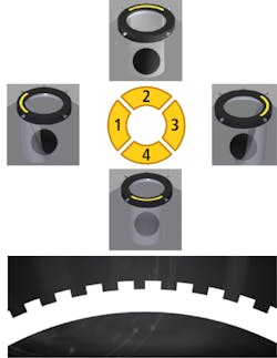
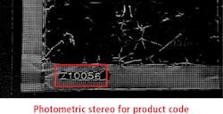
With a primary purpose of accentuating the 3D surface structure of an object, photometric stereo separates the shape of an object from its 2D texture. The technique works by firing segmented light arrays from multiple angles and processing the resulting shadow images in a process called shape from shading (Figure 5).
Photometric stereo outputs two images: a shape image containing 3D information and a texture image showing surface coloring without interference from surface structure. The technique enables the enhancement of surface details like scratches, dents, pin holes, or raised printing (Figure 3), while also enabling the removal of glare from reflective surfaces (Figure 6). On surfaces with 3D structure but little-to-no contrast, photometric stereo is especially effective. (Figure 4).

Multispectral imaging
Multispectral imaging enhances images with maximum contrast from multiple spectral bands. The technique works with samples or objects that respond to different spectral bands, typically UV, visible, and IR. This example involves the inspection of print and the detection of breaches in the foil, verification of UV marking, and lot code reading.
Highly-reflective foil makes imaging and lighting difficult. Near-infrared light enables the viewing of pinpricks and other foil breaches through print, while UV is necessary to see dye marking (Figure 8). With multispectral imaging, creating a sequence of three images—one for each spectrum of interest—is possible. The UV band reveals the UV dye, the visible band reveals the print, and the NIR band reveals the foil punctures (Figure 7).
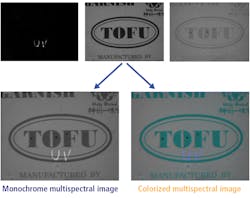
Through a weighted filter, a single composite image can be created to display the information in each of the spectrums, and the output image can be monochrome or pseudo-color to best show contrast. Some LED controllers can create multiple sequences of computational imaging functions (Figure 9). A total of seven images are needed to perform the multispectral analysis (three frames) plus the photometric stereo analysis (four frames).
CI represents a powerful technique for enhancing images for machine vision. While not intended as a replacement for conventional single-shot imaging, CI is a complementary tool offering reduced development time and better machine vision solutions.
Marc Landman is the Senior Technical Advisor at CCS America (Burlington, MA, USA; www.cssamerica.com) and Paul Downey is the Marketing Manager for CCS Inc. (Kyoto, Japan; www.ccs-grp.com).
This story was originally printed in the November/December 2019 issue of Vision Systems Design magazine.