How Lens Design and Tolerances Affect Imaging Performance
By: Jeremy Govier, Senior Principal Engineer; Greg Hollows, Vice President of Product Strategy and New Product Development; and Kyle Firestone, Technical Marketing Engineer for Edmund Optics
The quality of an imaging system depends on how well the system performs for a given application. Performance depends on the individual constituent components and how well these components interface together. To ensure the performance standards, component specifications must be derived from the specific application requirements.
Each component of an imaging system, including the optical imaging lens; machine vision camera; and illumination source, to name a few, contribute to the level of complexity the overall vision system. However, the content of this article will be restricted to discussing the design and manufacturing challenges for optical imaging lenses.
Optical Design Performance
While the term performance is somewhat subjective compared with the specific requirements of an application, contrast and resolution are two of the most fundamental performance indicators for vision systems. As such, lens performance is typically specified with a percent contrast as a function of resolution frequency, and called the modulation transfer function (MTF). Figure 1 shows an example of an MTF curve.
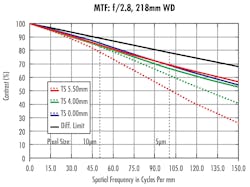
There is a fundamental limit, based on the aperture size and wavelength, to how well an optical system can perform. The diffraction limit is the upper limit to which all optical systems can reproduce object detail. This detail, which is measured in dimensional length units, is inversely proportional to (i.e. the reciprocal of) resolution, measured in contrast cycles or black and white line pairs, per millimeter (lp/mm) and with a specific contrast percentage.
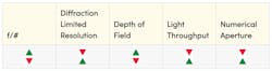
As mentioned previously, imaging performance may not always be limited to MTF. However, most other lens requirements can be tied directly back to MTF and a combination of some other lens properties or settings, such as the F-number (f/#) aperture setting.
Designing for Manufacturability
There are a number of ways in which a lens design may not be ideal, broadly speaking, or even possible to manufacture, assemble, test, or to install into an application. Lens design software is an extremely powerful tool, yet it does not replace the need for careful attention to detail or considering the unique nuances of optical manufacturing. A successful lens design requires close attention to manufacturing tolerances. Analytical and statistical methods for predicting and modelling tolerances during the design process are useful tools for controlling them during the assembly process.
Glass Tolerances
The index of refraction and the dispersion (abbe number) will vary from lens to lens and lot to lot in manufacturing. These changes are small but can affect the design’s performance and need to be properly modeled in a lens design’s tolerances . Small changes in index can affect the focus as well as aberrations like spherical aberration and coma, while changes in abbe number will affect both lateral and axial color correction.
Wedge, Roll, Tilt, and Decenter
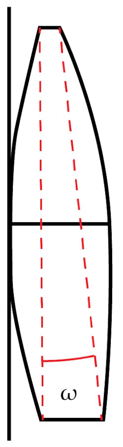
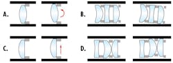
For every optical surface, element, and optomechanical constituent of a lens design, there are many tolerance contributions to be considered. Between the two primary surfaces of an optical element, there exists some amount of wedge, seen in Figure 2. Wedge is measured in angular units (usually arcminutes) and can be thought of as the tilt of one surface with respect to the other. This angle can also be calculated from the difference in length of the center thicknesses divided by the diameter of the clear aperture (Equation 1).

Where ω is the wedge angle, ΔCT is the difference between the maximum and minimum center thicknesses, and CA is the clear aperture diameter of a spherical lens.
Roll and decenter of elements are factors that can affect subsequent elements in the subassembly. Roll, similar to wedge, imparts a title of the element from nominal placement. However, roll will tilt the entire element about one surface.
Figure 3a shows an element that has roll because of the way the spherical surface is in contact with the neighboring spacer. This roll manifests as an angular deviation as well as a linear shift upward and toward the barrel. If this optical element had a plano surface or a flat ground annulus as in Figure 2, C, the element would only experience decenter. Depending on the shape of the element being rolled or decentered and the subsequent coupled elements, additional shifts from the nominal orientation may occur.
Modeling wedge, roll, and decenter tolerances in optical design software is conducted with Monte-Carlo simulations where, for each element or groups of elements, the amounts of decenter and angular motion, known as tilt, are varied. These simulations assume that all angles involved are small enough such that the small angle approximation is valid. For spherical optics with angular deviations, surface tilt from wedge and surface tilt from roll are indistinguishable because of symmetry from spherical geometry. Per element, one of the two surfaces is fixed (typically the surface closest to a fixed seat) while the other surface is tilted. Tilt from both wedge and roll effects from mounting are added separately into the tolerance model.
The effects of each of these deviations from nominal behavior can and do degrade performance and imaging quality individually. However, these effects also compound. It is important to note that a skilled designer, in accounting for overall optical performance, may choose to intentionally introduce an amount of tilt or decenter up front and in earlier elements to compensate for tilt or decenter effects in elements or groups in the design downstream.
Designing for Manufacturability Despite Tolerances
With all the different types of tolerances that can affect the design of an assembly, there are a number of ways in which optical designers and manufacturers are able to ensure successful production and with acceptable yields. The first method is to desensitize the design to the effects of tolerances.
Desensitize the Design
Optical designs with less sensitivity to tolerances are typically much simpler designs with fewer complex and specialized components. Thus, they are easier to manufacture, both reliably and repeatably, and in higher yields. The tradeoff with less complexity means that these designs will struggle in systems for which they are not directly designed. The solution a design software optimizer will find is often not the same as a design that will have the best as-built performance. There are many tools available to a designer to optimize for a desensitized design that will give the best toleranced performance including: using optimizer tools built into lens design software, adding configurations with perturbed element to design around sensitive tolerances, and putting constraints on surface refractions and surface aberrations. All of these methods attempt to balance the overall design’s refractive efforts across all of the elements so that no singular element acts as pinch point. This way, if a design is perturbed by a tolerance, there will be fewer severe effects on the system level performance.
Tighten Tolerances
When a design can no longer be desensitized to tolerance effects , the next options is to tighten tolerance specifications. There are two main ways to obtain components with tighter tolerances. The first method is to sort, within a production lot, for the quality needed and scrap the parts that do not meet the requirements. This method is typically more useful when the reliability of the quality of produced parts is well-modeled with a statistical distribution. For example, typical automated centering processes will result in nearly all produced parts having 1 arcminute of beam deviation or less. However, some hypothetical percentage of these parts may meet a 0.5-arcminute deviation. If 80% of parts have 0.5 arcminutes of deviation, the cost of the remaining 20% (the scrapped parts) will be passed along to the customer.
The second way in which tolerances may be tightened is by changing the manufacturing process or process conditions. Manufacturers may require more powerful or specialty equipment. However, the cost of this equipment as well as the cost of maintaining and operating it is also more costly. These additional margins will also be passed along to the customer.
Tolerance Compensation
When designs cannot be desensitized or tightened, manufacturing methods that make use of a feedback mechanism may be used to compensate for these tolerance effects. Active alignment is an assembly technique that uses special barrel assemblies with access holes to align optical elements as they are assembled. With active alignment, there are two primary ways to reduce tolerance effects . One method is for the assembly technician to reduce as many forms of tilt and decenter in the stack-up as possible. However, this option takes additional assembly time and is limited by the manufacturing precision for each of the elements. The other way that active alignment may be used is with some upfront, built-in design flexibility. Tolerances downstream in a design may be mitigated by adjusting an upstream component while monitoring performance metrics.
For example, element thickness, radius, refractive index, or mechanical seating tolerances will deviate the nominal ideal focus position. A designer may adjust the air gap between the last element and the sensor while measuring image quality in the form of MTF to compensate for these errors. However, tilt and decenter require more complicated compensations than what is required to compensate for focus. Adjusting the tilt or decenter of an element or group of elements while comparing performance can compensate for all the other tilts and decenters in the system. The adjusted element or group of elements may be intentionally decentered more than normal. But, put in the context of the overall performance of the system, this decenter may be the best position to correct for all other errors. This method is not a one-size-fits-all solution and is therefore not always successful.
Conclusion
Imaging lens performance is defined in a few key ways. However, most designers, manufacturers, and end users specify this performance with the modulation transfer function: contrast as a function of resolution. For high-performance imaging lenses with highly complex optical designs to be manufacturable, considerable time, effort, and often cost are factored into the design and the plan for the production process. For high-volume production, this can be especially troublesome as complex designs require non-standard or highly advanced manufacturing techniques to create and assemble optical elements. Even once all the constituent components have been manufactured, tolerance effects and considerations for mitigating these effects, on both the individual component level and the scale of the overall stack-up, must be balanced to meet overall performance specifications. For these reasons, it is critical for end users and integrators to understand exactly what performance specifications are required.