Vision system checks engine-manifold integrity
Smart cameras, LED lighting, and imaging software inspect bolt holes.
By Earl Yardley
Intake or inlet manifolds form the part of an automobile engine that supplies the fuel/air mixture to the cylinders. An exhaust manifold collects these exhaust gases from multiple cylinders and channels them into one pipe.
One of the largest polyamide intake modules for passenger cars is currently made by automotive-systems supplier Mahle Filtersysteme. Designed using polyamide reinforced with glass fibers, these flow-molded manifolds must be perfectly formed to fit to the cylinder head of the engine. If the mix of polyamide and glass fiber is not correct, shrinkage of the manifold will occur, resulting in an improper fit. In addition, the injection-molded manufacturing process may introduce unwanted artifacts that need to be repaired before final assembly.
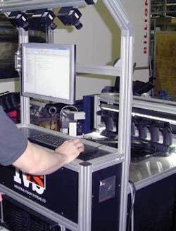
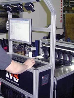
To ensure the integrity of these manifolds, Mahle Filtersystem called upon Industrial Vision Systems (IVS) to develop an automated system that checks the bolt holes used to mount the manifold to the engine. After each manifold is formed using a flow-molding machine it is automatically placed into a test rig using anx-y-z positioning system from Sepro Robotique.
Through holes
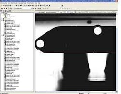
To image the through-hole bolts on such a large part, the manifold is illuminated with a high-intensity, 46-in. white linear LED Monster light from Spectrum Illumination. By placing the manifold on a white reflective-plastic background, white light is reflected through all seven of the manifold’s bolt holes (see Fig. 1). This reduces the cost of the illumination required and ensures that light is evenly reflected through the bolt holes.
Before any inspection of these holes can be done, a single FWX 13C FireWire camera from NeuroCheck images a blow-by pipe that forms part of the manifold. These pipes vent blow-by gasses, a mixture of unburned fuel, air, and combustion products that leak past the engine’s piston rings while the engine is running. These vents avoid pressurizing the crankcase, which would otherwise force oil from the engine. Measuring the width of this pipe ensures the accuracy of the flow-molding process and, once verified, that further bolt-hole inspections can take place.
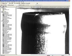
This blow-by pipe requires special illumination to ensure that it can be imaged correctly. Using a white LED spotlight, also from Spectrum Illumination, light is directed to one side of the pipe and reflected back from the rear of the manifold. This light creates a silhouette of the pipe that presents the imaging system with white-on-black and black-on-white edges of the part that can be easily measured (see Fig. 2).
Regions of interest
After images of the blowhole are transferred to a host PC, NeuroCheck software measures the diameter of the part (see Fig. 3). As images are captured, a calibration routine determines the real-world values that make up each pixel. After calibration, two independent look-up tables (LUTs) are applied to the image. The first, a quadratic LUT, is used to highlight the contrast between the light and dark edges of the blow-by pipe. The second, a Guassian LUT, applied in succession, forms a sharp edge transition between the pipe and the background image.
Two regions of interest (ROIs) are defined at the right-hand and left-hand side of the image. A threshold level within these ROIs is then set and the edges of the pipe are determined. After this, a simple software gauge measures the distance between them. This measurement is correlated with known part variances and the blow-by pipe either accepted as a known good feature or, in the case of a failure, used to indicate to the operator that the flow-molding process is inaccurate.
Once each blow-by pipe is verified, the bolt holes used to attach the manifold to the engine block are inspected. To determine the distance between the holes, the centroid of each hole must be calculated. To do this, three FWX 13C FireWire cameras are positioned on an overhead gantry in such a way that each camera images three bolt holes. Attached to the system’s PC, images from all three cameras are transferred to the host PC for processing. To determine the distances between each of the bolt holes, the centroid of each hole must be determined and the distance between each hole then computed. Because three bolt holes are imaged with each camera, the distances between individual holes can be determined.
For each of the three cameras in the system, the same image-processing functions are performed. After calibration, ROIs around each bolt hole are defined and two Gaussian LUTs applied to enhance the contrast between the black manifold background and the white bolt hole. After the LUTs are applied, an image-smoothing function is applied to the ROIs to reduce the effects of camera noise, and spurious or missing pixel values.
After determining a threshold value within each ROI, each bolt hole can be determined and the Compute Model Geometries feature within NeuroCheck used to map a best fit circle to the circumference of the hole. Once computed, the centroid of the bolt-hole is determined using a gauge ROI function. This process is then repeated to find the centroids of all the bolt-holes on the manifold.
Linear measurements
To calculate the proper linear measurements between all seven bolt holes, each camera images three centroid measurements. The system must generate a global measurement list that accurately describes the distance between individual bolt holes and the distances between the two that are farthest apart. Because each camera images three such holes, the distance between the first three, second three, and final three can be measured by computing the distance using images from each of the cameras.
By overlapping captured images, data from camera one and two can be combined to provide a measurement list across seven holes. Then, by using data from the third camera, a measurement list is created that shows the distance between all seven bolt holes. In NeuroCheck, the Combine Measurement list is used in two stages to determine the data.
After each blow-by pipe and bolt hole is inspected, integrated industrial control functions within the NeuroCheck software send I/O data to the programmable logic controller integrated within the Sepro Robotiquex-y-z positioning system. Should a part fail the test, then the manifold is rejected. Parts that have passed inspection are moved to a separate conveyor system, where they are packaged for shipping to automotive suppliers.
Hot and cold
Each manifold is presented to the inspection system as it emerges from the flow-molding system to be inspected while hot. Dimensions of such parts will be slightly larger than those of the finished shipped parts. To account for this, single parts are removed from the flow-molding system by the robot at hourly intervals and allowed to cool. These are then repositioned within the machine-vision system, and the parameters of the blow-by pipe and the bolt holes measured.
Because there is a known shrinkage that occurs during this process, the values generated are compared with those of known hot parts. By comparing these differences with known calibration coefficients, NeuroCheck can alert the operator as to whether the flow molding system is performing as expected.
Mahle is using the system to guarantee 100% quality of parts produced. The use of the NeuroCheck software means that Mahle engineers can understand and use the vision system after minimal training. Mark Kneller, mold-shop engineering manager with Mahle, is impressed with the technology used in the vision system. He says that the detailed subpixel measurements that the IVS system provides offer real-time in-process gauging as opposed to the previous method of slow, off-line inspection.
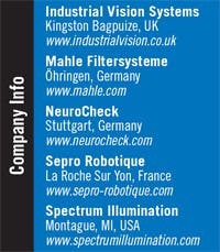
Earl Yardley is director, Industrial Vision Systems, Kingston Bagpuize, UK; www.industrialvision.co.uk.
null
