Automation speeds sawmill inspection
Custom vision system uses CCD imaging, laser triangulation, and three-board image-processing packages.
By R. Winn Hardin, Contributing Editor
Machine-vision systems in the lumber industry are gaining acceptance as productivity tools that can save sawmills great expense each year. In some sawmills, machine-vision systems are located at multiple spots along the lumber production and finishing lines to perform various tasks, from inspecting and evaluating rough logs to maximizing the amount of finished lumber per log, to inspecting the lumber in its stages from rough cants to finished boards for dimensional accuracies to within a thousandth of an inch.
To increase productivity, the sawmill must squeeze more lumber from each log. The application is among the most challenging facing the machine-vision industry-being both high-speed (running at up to 10 m/s) and based on an automated system that inspects organic products with defects that are almost never the same.
In a sawmill, vision systems take two general forms. Laser triangulation systems make accurate, fast dimensional measurements of the lumber, such as thickness, width, length, planarity, warp, and bow, which can be used to grade the lumber and monitor the performance of saws and other production equipment. Automated optical inspection systems use area-array sensors to collect information about surface defects, which need to be removed further down the production line.
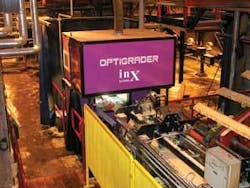
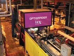
Working with a team of vision-algorithm designers led by Olli Silven of the Information Processing Laboratory at the University of Oulu in Finland, vision-system integrator inX Systems designed the OptiGrader lumber-grading and optimization machine-vision system for international lumber-products producer UPM. The system uses three area-array CCD cameras matched to laser linescanners to measure and track boards in three dimensions, while a pair of linear-array color cameras find and report surface defects, such as knots and burns.
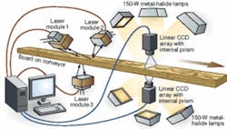
In one deployment at UPM, an inX OptiGrader system uses three laser triangulation modules, with each module consisting of a laser line generator and 1048 × 1240-pixel CCD, to make spatial measurements of finished lumber. The system also uses two 2048 × 3 pixel linear-array CCD modules with internal prisms for separating the RGB color constituents and flat-emission metal-halide lamps to find surface defects for real-time surface inspection. Each module is supported by three image-processing boards mounted in an expanded-tower generic PC host running Windows XP, with additional PCI card slots on the motherboard (see Fig. 1).
Building bandwidth
According to inX CEOJyri Paavola, each imaging module uses a group of three proprietary image-processing boards, including a PCI-based motherboard and I/O board-each with a single digital-signal processor. A slave board attached to the motherboard hosts four DSPs. The motherboard interfaces with OptiGrader supervisory software and a user interface running on the PC, while the I/O board does the A/D conversion on the camera signal and communicates with actuators, ejectors, and other nearby PLCs to direct the wood along different conveyors after grading. The slave image-processing board with four DSPs performs all image-processing functions, from image normalization and lens-distortion correction to color histogram analysis (see Fig. 2).
inX either designs or manufactures all the modules and components, with the exception of the illumination systems (laser line generator and metal-halide lamps), including cameras and image processors, for several reasons. It is easier to guarantee the highest performance and long-term support of components, and the requirements of high-speed lumber grading mean that a robust system has to be engineered to the highest specifications.
Making the grade
As the first board comes into the inspection station, it crosses three projected laser lines: two reflecting off the board from a pair of laser line generators located off the optical axis above the board and a third line projected through an opening in the support conveyor. A pair of 1024 × 1240-pixel CCD cameras positioned above the board and a third below the board capture deviations in the laser line caused by the board. While one of the triangulation modules located above the board and the module below the board send image data through the I/O board and into the slave image-processing board to measure the board with six degrees of freedom (three dimensions and three orientations), the third triangulation module measures the movement of the board as it travels through the inspection station.
“Regardless of the quality of vision components, the accuracy of transverse scanning systems suffers from vibration and the uneven/jerky transport of pieces across the scan zone. Scan accuracy further suffers if a system turns a piece upside down for scanning its multiple sides because software cannot accurately put all scanned data together for a reliable optimizing decision,” Paavola explains.
inX uses a linear scanning system that scans the log as it moves lengthwise through the laser line instead of crosswise (transverse) or scans the entire log while stationary (snap shot). Linear scanning benefits from a smaller inspection window that’s as wide as the log is wide, rather than as wide as the log is long. This allows the integrator to position linear-scanning cameras closer to the log surface, which improves the system’s spatial resolution without requiring more expensive optics and can require fewer sensors because there is less area to cover.
inX triangulation modules operate at 400 frames/s at full resolution, or 800 frames/s at half resolution (512 × 620 pixels), depending on desired throughput, required spatial resolution of the application, and standoff. The final dimensions of the board are determined on the third module’s image-processing board and passed to the PC for storage on the sawmill plant network for later statistical analysis (see Fig. 3).
Signals are sent to the relevant PLC if the board’s dimensions fall below a certain threshold, and alarm signals are sounded if the dimensional differences warrant operator attention to the machinery. Many saw blades in a mill are sharpened over six to eight hours, and 1/1000-in. additional wood per cut can mean several hundreds of thousands of Euros to mill operators each year.
When color is critical
The surface-defect inspection and classification portion of the system locates surface defects based on small variations in color and connected component analysis. Says inX’s Paavola, “Inx Systems is a proponent of full-color lumber scanning, due to the fact that color images contain so much more data. Until recently, it has been impossible to color scan and to process these high volumes of data at sufficient rates. This and more-demanding defect detection/analysis/classification requirements on the software and hardware are the main reasons why a majority of grade scanner manufacturers only offer B/W cameras in their systems.”
He adds, “Spectral or multispectral scanners simply uses a B/W or other monochrome camera that is tuned to one or more wavelengths by either blocking certain wavelengths with optical filters or by emphasizing certain wavelengths with light sources that emit colored light. Lack of full-color image information put these systems into the same handicapped position as B/W camera systems, or even worse, since these systems actually have fewer data available to be processed than B/W scanners. The reason for using multispectral arrangements is the same as for using B/W cameras: a limited data-processing capability and complexity of reliably analyzing full color image data with existing technologies other manufacturers have available today.”
According to Paavola, color by itself is not enough. inX chose a color sensor that uses a prism inside the 2048 × 3-pixel linear CCD camera to separate the color components of the incoming visible light signal into red, green, and blue. Using a central prism with separate sensor arrays means the camera maintains greater spatial resolution with less fill factor than cameras that use groups of three pixels with on-chip filters to detect color. inX also pays close attention to the sensor’s dynamic range and builds its cameras using a high-quality OEM sensor that offers low readout and dark-current noise, which is important when digitizing analog signals at the extremes of the color space.
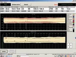
This attention to signal fidelity allows the OptiGrader to locate and classify defects using a combination of color histograms of 32 × 32-pixel blocks followed by connected component analysis to identify defects in the wood. Depending on the type of inspection, additional algorithms such as edge detection and blob analysis may be used to further filter and identify wormholes, knots, and other defects from raw image data (see Fig. 4).
High-grade appreciation
“We have been quite satisfied with the OptiGrader system,” says Risto Laaksonen, materials manager for UPM. “It’s able to detect the defects in the wood. The most important ones are the knots, and knots can be divided in different categories as wet and dry knots. This system can separate them quite reliably; that is actually the critical part when you try to sort lumber. The other is the shape of the piece, and the OptiGrader is very accurate in that sense, as well.
“But perhaps the most important difference among systems,” says Laaksonen, “is the ability to detect the knots the same way every time so you don’t have to adjust the system every month. Once you have tuned it up, then it works. And in that sense, it’s quite user friendly. You don’t have to look after it all the time, and other systems you do have to look after. They tend to roam, and are not stable in defect classification.”-RWH
Company Info
inX Systems
Kerava, Finland
www.inxsystems.com
University of Oulu, Information Processing Laboratory, Department of Electrical Engineering
Oulu, Finland
www.ee.oulu.fi
UPM
Helsinki, Finland www.upm-kymmene.com
