Choosing a camera for infrared imaging
Before choosing an infrared (IR) camera, developers must understand the different types of IR detectors, cameras and specifications and how these can affect system performance.
Markus Tarin
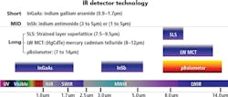
The infrared spectrum is divided into near-IR, shortwave (SWIR), medium wave (MWIR) and long wave (LWIR). To detect radiation at these wavelengths, a number of different detector technologies are used. While shortwave IR sensors are typically composed of Indium Gallium Arsenide (InGaAs), MWIR sensors typically rely on Indium Antimonide (InSb). SWIR and MWIR detectors can be actively cooled, increasing sensitivity and at the same time adds to the cost of cameras based around them.
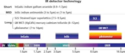
In the LWIR range, Mercury Cadmium Telluride (MCT) and Strained Layer Superlattice (SLS) detectors provide a high-level of temperature precision. However, both technologies require active cooling, which increases cost. A lower cost, albeit less sensitive option in the LWIR, is the microbolometer, typically found in less expensive handheld cameras. For many applications, microbolometer-based cameras provide an affordable alternative to those that are actively-cooled. The wavelength ranges of all these detectors is illustrated in Figure 1.
Thermography (IR thermal imaging), is a method of a non-contact temperature measurement using a temperature-calibrated IR camera. Thermal energy detected by IR cameras is not visible to the human eye, so the different temperatures in a thermal image may be "mapped" to different colors for display using IR visualization software (Figure 2). As temperatures change, the colors in the image change, alerting users to possible areas of concern or out-of-spec conditions. Selecting the most appropriate color palette can help highlight the critical features in a thermal image.
Accurate measurements
Understanding the relative temperature differences in a color-mapped thermal image is easy but if accurate temperature measurements are required, a number of potential error sources must be considered. These include the emissivity of the surface being measured, the viewing angle of the camera, surface reflections, the transmission characteristics of the target, atmospheric attenuation, spatial resolution limitations and motion blur. If one or more of these considerations are overlooked, temperature accuracy will suffer.
Temperature measurements captured by a thermal camera consist of transmitted, reflected and emitted energy, the measured temperature being the sum of these three energy components. Transmitted energy is the energy passing through the object while reflected energy is the energy reflected from the target to the camera. Emitted energy is the energy generated by the target. Generally, when measuring the temperature of an object, the emitted energy is of primary concern.
If the camera is mounted at an angle, some fraction of the emitted energy will be lost, and the more the angle increases, the less emitted energy that will be detected and the greater the measurement error. Thus, it is best if the camera's sensor is aligned parallel to the target surface.
Reflections are another source of error. Hot objects in the vicinity of the target being measured may reflect from the target. Since the total temperature includes reflected energy, any reflections can mask emitted energy and degrade measurement accuracy.
Depending on their physical characteristics, some targets may have transmission issues. Thermal cameras can see through some types of materials, particularly some plastics. Thus, it is important to ensure that a lot of energy is not being transmitted through the object being observed, otherwise the temperature behind the target may be detected rather than the surface temperature.
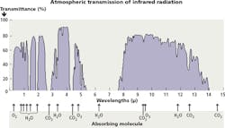
Thermal radiation is blocked by certain molecules in the air (Figure 3). Attenuation bands are caused by molecules that absorb energy at a given wavelength. For example, the gap between 5.5 and 7.5μm is due to moisture (water) molecules in the air that completely absorb the IR radiation. When selecting a thermal camera, systems developers need to be aware of these absorption bands and, when possible, adjust for them.
Camera considerations
Good quality IR cameras have a temperature accuracy of about +/-2o Celsius, or 2% of full scale, whichever is larger. Unfortunately, it does not matter whether the camera costs $5,000 or $100,000, the accuracy is not much better than +/-2 °C. If more accurate measurements are required, the use of thermocouples may be a better option.
There is a reason why there is a large price difference between calibrated thermography cameras and un-calibrated cameras. High end, factory-calibrated IR cameras require that precise temperature calibration is performed in a laboratory. Such cameras also need to compensate for the temperature drift of the detector, which requires a temperature sensor and compensation electronics inside the camera. These features are typically not included in lower-cost, non-calibrated cameras.
There is an iris-type shutter, or a flag next to the detector in IR cameras that is used to compensate for temperature drift. Periodically, clicking noises may be heard from a thermal camera indicating that the flag has been dropped in front of the detector, and the camera is recalibrating to compensate for thermal drift. This automatic calibration typically takes a few seconds, executing during startup or if the camera detects an internal temperature drift. This temperature recalibration needs to be taken into consideration for automated imaging applications because the camera is "blind" during recalibration and the continuous image data stream will be interrupted.
NETD Values
Noise-equivalent temperature difference (NETD) defines the detector's ability to distinguish between very small differences in thermal radiation in the image. A typical NETD of an uncooled microbolometer is somewhere below 50milliKelvin (mK). Cooled cameras that are photon-based, or have photon-based detectors provide better than 20mK. Thus, if a high-degree of measurement sensitivity is required, a cooled camera may be needed.
In cameras with multiple measurement ranges, the NETD depends on the selected measurement range. The smaller the temperature range, the better the NETD. Matching the NETD of the camera to the application is important and this is particularly true if lower temperatures need to be measured or the application requires greater temperature precision.
Application considerations
When choosing a camera, it is important to know the field of view and how large is the smallest feature.
Typically, at least 3 x 3 pixels across the smallest critical feature in your image will ensure adequate coverage and at least one pixel will read the true temperature of the feature. If the smallest feature is covered by only one pixel, it is unlikely that the single pixel will align exactly with the feature. It is important to perform these spatial resolution calculations to ensure that accurate measurements on the smallest features are made.
If moving targets need to be imaged, it is important to understand how fast the target moves through the field of view of the camera or, more specifically, the distance (in pixels) that the target moves during the integration time. With higher-end cameras, such as those with a mid-wave InSb detector, a shutter integration time of 0.056ms is possible. Using such a camera, the temperature or other aspects of the surface of the object can be measured without introducing thermal smearing caused by motion blur.
IR and thermal camera lenses are very different from machine vision lenses since lenses need to be calibrated to the camera's sensor. Lenses are made from exotic and expensive materials, such as Germanium, Zinc Selenide, or Sapphire that transmit specific IR wavebands and are matched to the detector of the camera. IR lenses are also often athermalized to avoid focus drift, which also adds to the cost.
Protective enclosures are also necessary when installing cameras in hostile environments. Since IR cameras cannot look through standard glass windows, camera enclosures require exotic windows of Germanium, Zinc Selenide or Sapphire. The window material must be matched to the specific camera and the environment.
Thermal cameras offer several different communication interfaces, including standard Ethernet, GigE (with GeniCAM compliance), Camera Link, CoaXPress, USB, and proprietary interfaces. Using a camera with a GigE interface with GeniCAM compliance allows the use of off-the-shelf development tools to be used and circumvents the need to deal with proprietary communications protocols. Such systems can support camera to computer distances up to about 300 feet without a switch. For longer runs, fiber-optic extenders allow many digital standards to be transmitted over fiber, extending working distances to several miles.
Markus Tarin, President and CEO, MoviTHERM, Irvine, CA, USA; http://movitherm.com


