CMOS imagers look to increase dynamic range
Andrew Wilson, Editor
In many industrial and automotive applications, it is necessary to capture images that may simultaneously contain very bright and very dark components. In automotive applications, the imagers expected to perform this task are required to capture scenes in both daylight and nighttime conditions. Such sensors must be capable of capturing images with intensities that may vary over a dynamic range of 100dB range or more.
This dynamic range is defined as the ratio of the largest non-saturating input signal to the smallest detectable input signal. Consequently, increasing the dynamic range of CMOS and CCD imagers is achieved either by increasing the largest non-saturating input signal or decreasing the smallest detectable input signal. In most high dynamic range (HDR) imagers, the former method is used.
Several techniques and architectures have been proposed for extending image sensor dynamic range as Daniel Van Blerkom, co-founder and CTO of Forza Silicon (Pasadena, CA, USA;www.forzasilicon.com) points out in his article "CMOS Detectors: New techniques recover dynamic range as CMOS pixels shrink", Laser Focus World, June 2010; http://bit.ly/1rCSlEe). These can be classified into two main techniques: those that modulate the exposure time of the pixels and those that modulate the conversion gain of the pixels.
Today, a number of companies such as Awaiba (Madeira, Portugal;www.awaiba.com), CMOSIS (Antwerp, Belgium; www.cmosis.com), IMS Chips (Stuttgart, Germany, www.ims-chips.de), ON Semiconductor (Phoenix, AZ, USA), Melexis, (Concord, NH, USA; www.melexis.com) and Photonfocus (Lachen, Switzerland; www.photonfocus.com), use these techniques to increase the dynamic range of their image sensors (see "Dynamic design," Vision Systems Design, http://bit.ly/1lFaDBs).
Modulating exposure time
To acquire a high dynamic range of a scene, parts of the image that appear bright must be captured simultaneously with those that appear dark, without saturating the high-brightness pixels. To do so, the integration time of pixels with a higher well capacity are reset during the integration time while those with a lower well capacity are given a longer integration time.
A number of different companies have used this technique to increase the dynamic range of their image sensors. These include Photonis (Merignac, France;www.photonis.com), in the design of its Kameleon CMOS imager.
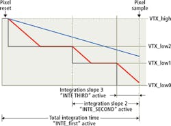
Supporting frame rates up to 100 fps at 1280 x 1024, the imager is used in the company's NOCTURN U3 color camera. Using the Kameleon imager, pixels which reach a programmable voltage will be partially reset - a process that can be performed twice during the integration period (Figure 1). Bright pixels (represented by the red line) represent a pixel where large amounts of electrons are collected and the blue line represents a pixel with fewer electrons being collected. Bright pixels are held to a specific voltage for a programmable time during the exposure. This happens twice to ensure that at the end of the integration period, the pixel is not saturated. Darker pixels are not influenced by this multiple slope and will have a normal response.

Rather than use this approach in its high dynamic range series of CMOS imagers developed for automotive cameras, security cameras and tablet applications, Toshiba (San Jose, CA, USA;www.toshiba.com) uses a single frame method in which different exposure times are applied to different lines in a frame (Figure 2).
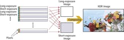
Since this method will generally provide a lower resolution in the vertical direction, Toshiba's image sensors for smartphone and tablet applications provide twice the number of pixels necessary in the vertical direction. Since the high dynamic range images that result from combining interline images with different exposure times result in pixels with greater than 10-bits of data, the data is then mapped using a tone-mapping technique to display the images on displays with a more limited dynamic range.
Conversion gain
While modulating the exposure time of the pixels can increase the dynamic range of CMOS imagers, other techniques that modulate the conversion gain of the pixels are often used. Here again, this can be achieved in a number of different ways. In the design of its range of sCMOS sensors, for example, Fairchild Imaging (Milpitas, CA, USA;www.fairchildimaging.com) uses an architecture that features a split readout scheme of odd and even columns.
As each pixel from each photosite is read out, dual amplifiers and analog-to-digital converters with independent gain settings are applied to the signal and combined to achieve a high dynamic gain. This architecture has been widely embraced by numerous manufacturers that now offer scientific cameras based on the company's sCMOS imagers (see "sCMOS cameras target scientific applications,"Vision Systems Design, http://bit.ly/1f6h9CW).
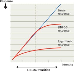
Achieving high dynamic gain can also be accomplished by using non-linear conversion gain modulation techniques using pixel architectures that exhibit a logarithmic response to light. One of the earliest commercial applications of this technique was the LINLOG technology from Photonfocus, a pseudo-logarithmic architecture that provides a linear response at low illumination levels and logarithmic compression at high intensities (Figure 3).
Other approaches include that from NIT New Imaging Technologies (NIT; Evry, France;www.new-imaging-technologies.com) in an architecture that uses a pixel design based on a photodiode operated in photovoltaic mode with the result that the open-circuit voltage across the p-n junction is proportional to a logarithmic value of the incident light intensity (see http://bit.ly/1tOgCZL).
Well capacity
Because the dynamic range of CMOS devices is related to the well capacity or the total charge each pixel can hold during integration, increasing this well capacity results in an increased dynamic range of the imager. Thus, although CMOS imagers with larger pixels may have a lower spatial resolution, the greater well capacity of such pixels will result in a higher dynamic range.
Well capacity and thus dynamic range will also be affected by the pixel circuitry required for charge integration and storage integrated into each pixel site. In active pixel imagers, both the photodiode and readout amplifier are incorporated at each pixel site. Because of this, the active photosensitive area of each pixel is reduced.
CMOS imagers designed to run in rolling shutter mode, for example, require a minimum of two transistors at each pixel site to transfer charge from the device. While such rolling shutters may produce image distortion artifacts when used for high-speed machine vision applications, the larger active photodiode area results in a higher dynamic range.
Global shutters
Operating such devices in global shutter mode, where every pixel is exposed simultaneously, eliminates such image distortion effects but requires additional circuitry to store the charge at each pixel site during the global exposure. Incorporating such additional circuitry allows such CMOS imagers to be operated in either rolling or global shutter mode but reduces the active image area further, lowering the dynamic range.
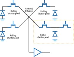
While both rolling and global shutter modes have their advantages and disadvantages, designers at Forza Silicon are looking to leverage the advantages of both in their next generation of high dynamic range imagers (Figure 4). The new design will take an unconventional approach replacing every fourth pixel site of a rolling shutter design with a global pixel site. By doing so, the high dynamic range of traditional rolling shutter designs will be preserved while at the same time, allowing every fourth pixel to take a global snapshot of the image. The global shutter data is used in subsequent processing to realign the data from the rolling shutter pixels - minus the rolling shutter artifacts.
To increase this dynamic range further, the imagers will use a sparse color filter pattern similar to that employed by ON Semiconductor in its Truesense Imaging sparse color filter pattern with each rolling shutter pixel site having a panchromatic or clear filter. Data from these pixel sites will then be used to interpolate the data from pixels in rolling shutter mode, thus reducing distortion artifacts while preserving the dynamic range of rolling shutter imager designs.
Companies Mentioned
Awaiba
Madeira, Portugal
www.awaiba.com
CMOSIS
Antwerp, Belgium
www.cmosis.com
Fairchild Imaging
Milpitas, CA, USA
www.fairchildimaging.com
Forza Silicon
Pasadena, CA, USA
www.forzasilicon.com
IMS Chips
Stuttgart, Germany
www.ims-chips.de
Melexis
Concord, NH, USA
www.melexis.com
New Imaging Technologies
Evry, France
www.new-imaging-technologies.com
ON Semiconductor
Phoenix, AZ, USA
www.onsemi.com
Photonfocus
Lachen, Switzerland
www.photonfocus.com
Photonis
Merignac, France
www.photonis.com
Toshiba
San Jose, CA, USA
www.toshiba.com