September 2014 Snapshots: Imaging system provides remote tech support, vision-guided military vehicles, camera-based eye surgery system, vision system measures plant photosynthesis
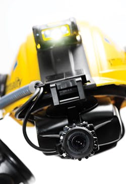
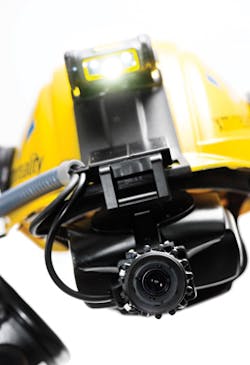
XMReality (Linköping, Sweden;www.xmreality.com) has developed a helmet system dubbed XMExpert that features a camera, microphones, headset, LED lighting and a PC that will allow a remote expert to see and hear what on-site technicians experience. It allows the technician to see and hear the expert, guided by real-time video images of the expert's hands as they direct a technician.
The mobile, helmet version of the system features a PC, video goggles, headset, noise-reducing microphone, LED light, and a 0.3MPixel Firefly MV FMVU-03MTC-CS global shutter CMOS camera from Point Grey (Richmond, BC, Canada;www.ptgrey.com).
The Firefly MV FMVU-03MTC-CS features a 1/3in MR9V022 global shutter CMOS image sensor with a 6 x 6 µm pixel size. The 0.3MPixel color camera achieves a frame rate of 60 fps and with this camera, the helmet captures the on-site technician's view and transmits images over a USB 2.0 cable to a computer running Windows 7. The display overlays the image from the remote expert's camera onto the image from the technician's field-of-view camera. The combined image is then fed back to the technician's helmet display.
"Both the technician and expert can work together as if both were standing in the same room," says Torbjorn Gustafsson, co-founder of XMReality.
Unmanned ground vehicles target military applications
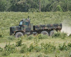
Oshkosh Defense (Oshkosh, WI, USA;www.oshkoshdefense.com) demonstrated the capabilities of its vision-enabled TerraMax unmanned ground vehicle (UGV) technology at the land and air-land defense and security exhibition Eurosatory 2014. TerraMax UGVs are designed to autonomously navigate in military route clearance missions and effectively provide additional safety measures in frontline military operations.
To navigate autonomously, each TerraMax UGV has multiple vision systems that consist of a trinocular system, a stereo camera system, a lateral camera system and a rearview imaging system. The trinocular system which uses three Point Grey (Richmond, BC, Canada;www.ptgrey.com) Flea2 cameras interfaced to a PC are located on the upper part of the windshield inside the cab and are used for obstacle and path detection. A stereo camera system, consisting of two Flea2 cameras mounted on a front camera bar and two on the back of the truck are used for close-range sensing,
The lateral vision system, which provides perception to detect oncoming traffic at intersections, consists of two cameras on either side of the front camera bar. The system employs two 1920 x 1080, 31fps Pike 2 cameras from Allied Vision Technologies (Stadtroda, Germany;www.alliedvisiontec.com). Finally, a rear view imaging system that employs two Flea2 cameras is positioned on the top of the cab looking backward and downward to detect passing vehicles.
Oshkosh is conducting its TerraMax UGV product development independently and also in collaboration with the U.S. Marine Corps and Army to identify opportunities to use UGVs for route reconnaissance and route clearance missions. These current projects build upon previous contracts with the U.S. Office of Naval Research for the Cargo UGV Project, which focused on bringing UGV capabilities to logistics convoy missions and reducing troops' exposure to threats.
Cataract surgery system features multiple cameras
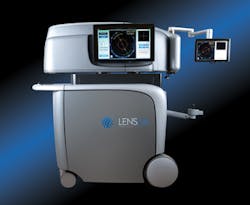
Built specifically for refractive cataract surgery, the LENSAR Laser System from LENSAR (Orlando, FL, USA;www.lensar.com) collects biometric data and reconstructs a 3D model of the anterior segment of the eye using a proprietary augmented reality technology.
In the LENSAR's augmented reality 3D imaging, measurement and guidance system is a 4Mpixel QUARTZ Qs-4A60 camera from Adimec (Eindhoven, The Netherlands;www.adimec.com) that the system uses to capture images at 60 fps. The augmented reality system rotates and captures anterior segment images at two different angles at up to eight different positions around the optical axis for a total of 16 potential images.
Multiple scans identify the precise location of the relevant anatomical structures from the anterior cornea to the posterior capsule and using optical ray-tracing, the system creates a 3D model of each patient's eye prior to surgery, allowing precise surgical incisions and treatment.
In addition, an Adimec A-1000 camera is also used in the LENSAR Laser System for alignment during the surgery. The camera achieves a frame rate of 50fps and features a dynamic range of 62dB and a Camera Link interface.
Vision system measures plant photosynthesis
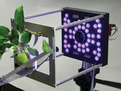
Scientists from Walz GmbH (Effeltrich; Germany;www.walz.com) have developed a CCD camera-based fluorometer that measures a plants' photosynthetic activity. The system was developed to determine how trees and crops develop in the field and to see how they react to parasites, fungal infections and climate change.
The level of photosynthetic activity in a plant depends upon its growth phase and health, and to determine plant health, Walz scientists created an imaging system called the IMAGING Pulse-Amplitude-Modulated (PAM M) Series that consists of a measuring head with integrated LED lighting and a digital camera.
Plant samples of different sizes can be placed in the measuring head, depending on the model. Samples are protected from outside light and are illuminated with light pulses from blue or red LEDs.
Three different measuring heads (Maxi, Mini, and Microscopy) are used in the system, each of which differs in terms of field of view. For the Maxi version, Walz chose a Manta G-145B GigE Vision camera from Allied Vision Technologies (Stadtroda, Germany;www.alliedvisiontec.com.) For the Mini version, a Manta G-033B GigE Vision camera was used.
Measurements begin with fluorescence stimulation using microsecond-short light pulses. Using the AVT camera, the fluorescence yield is measured, with the intensity of the measurement light being so minimal that it cannot trigger photosynthesis.
The next step involves a short, saturating light flash, and once again, the fluorescence yield is captured by the camera. At 400-800ms, this saturating flash is very short and can neither trigger photosynthesis nor damage the plant.
Following these two first steps, the ratio of the minimum and maximum fluorescence is computed and displayed with the value providing an indicator of the health of the plant.
Vision Systems Articles Archives
