High-speed imaging sheds light on secrets of flight
Using high-speed imaging and computational fluid dynamics, the unique mechanisms involved in mosquito flight have been revealed.
Dr. Simon Walker
Although a great deal is known about the behavior of mosquitoes, scientists have previously struggled to understand fully the aerodynamic principles that enable them to fly. Recently however, a collaborative effort between scientists at Oxford University (Oxford, UK; www.ox.ac.uk), the Royal Veterinary College (London, UK; www.rvc.ac.uk) and Chiba University (Chiba, Japan; www.chiba-u.ac.jp/e/) has provided an insight into the unique mechanisms involved in mosquito flight.
Well known carriers of diseases, mosquitoes' abnormally long, narrow wings and distinctive flight behavior set them apart from other insects. When flapped, their wings move back and forth approximately 800 times each second-faster than any other insect of comparable size. To compensate for these rapid movements, the angle through which their wings sweep (or stroke amplitude) is less than half that of any other insect measured to date.
However, the flapping pattern of short, fast sweeps means that mosquitoes cannot solely rely on the lift-enhancing mechanisms typically used by other insects. Research has now demonstrated that much of the aerodynamic force that supports their weight is generated in a manner unlike any previously described.
To reach this conclusion, a high speed imaging technique was employed to capture images of the mosquitoes in flight. Then, from the digitized outlines of the wing and body produced from an analysis of the moving images, a Computational Fluid Dynamics (CFD) model of the insect was created to show the airflow produced by their beating wings. The results of the CFD analysis were then compared to the results obtained from particle image velocimetry (PIV) experiments to verify their accuracy.
Imaging insects
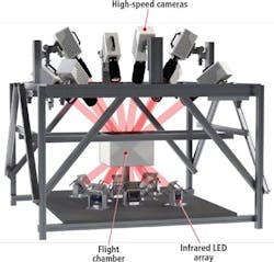
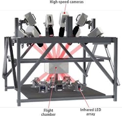
To capture images of the insects, eight SA3 high-speed cameras from Photron (San Diego, CA, USA; www.photron.com) were arranged to view a volume of 20 x 20 x 20 mm at the center of a transparent polycarbonate flight arena measuring 330 x 330 x 230mm designed specifically for the project (Figure 1). Theoretically, only two cameras are necessary to capture the 3D coordinates of an insect any instant in time. However, by using eight cameras, the imaging system could capture enough views of the mosquitoes to allow the images to be processed to discern wing motion.
In the experiments, the cameras were manually triggered to capture images of the mosquitoes as they entered the recording volume. The cameras, fitted with 180mm macro lenses from Sigma Corporation (Kanagawa, Japan; www.sigma-global.com) and Tamron (Saitama, Japan; www.tamron.jp/en) with an aperture of f/16, captured images at 10,000 fps with an exposure time of 5μs so that the motion of the wings of the mosquitoes could be recorded with no motion blur.
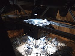
Infrared light was chosen as the preferred means to illuminate the insects during flight so that it would not disrupt their typical flying patterns. Consistent backlighting for each camera was provided by a set of eight coaxial, high-power infrared LEDs from Osram (Munich, Germany) built into custom enclosures. Divergent and Fresnel lenses from Edmund Optics (Barrington, NJ, USA; www.edmundoptics.com) mounted in front of the LEDs in the enclosures then collimated the light in paths of approximately 25 mm diameter towards each of the cameras (Figure 2).
Before performing the experiments, the eight cameras were calibrated using custom-written software running in MATLAB from MathWorks (Natick, MA, USA; www.mathworks.com). The software provides estimates of the camera parameters while simultaneously calculating the spatial coordinates of points on a 2D calibration grid in a series of positions and orientations.
To determine their flight behavior, fifteen recordings were taken of between 12 and 15 individual insects contained within the flight arena. Once a sequence of images had been captured and stored, the image data was transferred over a Gigabit Ethernet interface to a hub and from there to a PC, where the images were processed by custom image processing software written in MATLAB.
Image processing
As part of the processing, four points on the body of the mosquito were manually registered at every 1/15 frame in the image sequence - the base of the proboscis, the tip of the abdomen, and the left and right wing roots. These points were then used to calculate the 3D position and orientation of the mosquito body for each frame.
From the eight 2D images captured of each mosquito as it moved through the flight arena, image processing software created a volumetric 3D model of its body and wings. The model was then processed further to analyze the mosquito wing movements in great detail.
To create such a model, silhouettes of the mosquito were extracted from each of the eight images captured by the cameras using background subtraction. A further set of image processing operations were then performed on the silhouetted images to isolate the wings from the body in the images. A pixel thresholding technique, for example, was applied to the images to isolate and mask the body from the wings, since the body appears darker in the images than the wings. Skeletonization and dilation image processing functions were applied to identify, isolate and mask out the long, thin legs and antennae of the insect.
Using the eight 2D silhouetted images of the mosquitoes, an automated voxel shape-carving method was used to reconstruct 3D coordinates of the body and the wings of the insect. To do so, a cube of volumetric pixels (voxels) were projected onto each of the eight camera's viewing planes. Any of the voxels from the scene that then lay outside the pixel coordinates of the silhouette of the body or the wings of the mosquito were then discarded, while those that were inside the silhouette were retained. In effect, the process effectively "carved away" voxels in the cube that did not directly correspond to the pixels that represent the body or wings of the mosquito.
A 3D morphological model of the wings that could be used for CFD analysis was constructed by separating the voxels corresponding to the leading and trailing edges of the wings and fitting elliptical cubic splines to each edge from the wing base to the wing tip. The body surface, on the other hand, was extracted by manually fitting a series of ellipses to the body. Ellipses corresponding to both the body and the wings were then interpolated by cubic splines and used to generate a mesh surface for analysis.
Previously, most insect studies modeled the wing of insects as a flat surface. However, by fitting cubic splines to both the leading and trailing edges of the wings, it is possible to calculate how the pitch angle of the wing changed across its length, and from that ascertain its importance in insect flight.
Insect flight
Many insects enhance lift production through the creation of leading-edge vortices, which are rotational, bubbles of low pressure created along the front edge of the wing. These vortices create a pressure differential between the top and the underside of the wing that produces additional lift. While mosquitoes employ this technique, due to the small angle through which they move their wings, it was hypothesized that this could only be one of the contributing factors which enable them to fly. Indeed, the CFD simulation (Figure 3) revealed that the mosquitoes employ two other additional novel aerodynamic mechanisms known as rotational drag and trailing edge vortices.
Any wing or aerofoil that is at an angle relative to air produces both a lift force and a drag force. The lift force perpendicular to the oncoming airflow and the drag force is parallel to it. While the lift force is generally considered to be advantageous and drag detrimental, if the drag is orientated upwards relative to gravity, a force can still be created to support the bodyweight of an insect.
Indeed, the CFD analysis showed that the mosquito makes use of the drag force to support its weight by changing the axis about which its wings rotate during flight. Either the wing can be rotated about the front (or leading edge) of the wing, or it can be rotated about the rear (or trailing edge). By shifting the axis of rotation at specific instances in time, the drag force can then be directed so that it contributes to supporting the weight of the mosquito during flight.
In addition to making use of a drag force to support their body weight, the analysis also revealed that the mosquito also makes use of trailing edge vortexes. These are akin to leading edge vortexes, except that they are generated on the rear, or trailing edge, of the wing. By timing the rotational angle and velocity of the wing, the trailing-edge vortex is created on the upper surface of the wing during an upstroke due to the capture of the flow from the preceding down stroke. This in turn creates a region of low pressure on the upper portion of the wing which contributes to the lift of the insect (Figure 4).
Accurate model
To verify the accuracy of the CFD model, a Particle Image Velocimetry (PIV) system was deployed to calculate the speed and direction of flow around the wings of tethered mosquitoes in the center of the flight chamber. In the PIV experiments, the flight chamber was seeded with a mist of olive oil droplets which were illuminated with a sheet of light generated by a 10mJ dual-cavity pulsed laser from Litron (Rugby, UK; www.litronlasers.com). The scattered light from the insect was then recorded using a single Photron SA3 2,000 fps camera.
The PIV calculations were performed using Davis v.8.1.5 software from LaVision (Göttingen, Germany; www.lavision.de). To determine the flow around the wings of the insect, consecutive images captured by the camera were subdivided into small interrogation windows. The average particle displacement was then determined by cross-correlating the interrogation windows in the consecutive images which were separated in time, followed by localizing the correlation peak.
From the known time difference and the measured displacement in each direction, the velocity components of the flow were then calculated. The results, which were then compared with the flow around the wing created by the CFD model, showed a high degree of correlation, verifying the integrity of the model itself.
Because mosquitoes spread many diseases, such as malaria and the Zika virus, understanding the mechanisms that enable them to fly may enable researchers to develop more effective ways to reduce their damage to human health. Such flight techniques could also be employed by design engineers in the development of novel, next generation small-scale airborne vehicles.
Reference
Smart wing rotation and trailing-edge vortices enable high frequency mosquito flight. Richard J. Bomphrey, Toshiyuki Nakata1, Nathan Phillips and Simon M. Walker, Nature, Volume 544, April 6, 2017.
Dr. Simon Walker, University Research Fellow, Department of Zoology, Oxford University, Oxford, UK (www.ox.ac.uk)
Companies mentioned:
Chiba University
Chiba, Japan
www.chiba-u.ac.jp/e
Edmund Optics
Barrington, NJ, USA
www.edmundoptics.com
LaVision
Göttingen, Germany
www.lavision.de
Litron
Rugby, UK
www.litronlasers.com
MathWorks
Natick, MA, USA
www.mathworks.com
Osram
Munich, Germany
www.osram.com
Oxford University
Oxford, UK
www.ox.ac.uk
Photron
San Diego, CA, USA
photron.com
The Royal Veterinary College
London, UK
www.rvc.ac.uk
Sigma Corporation
Kanagawa, Japan
www.sigma-global.com
Tamron
Saitama, Japan
www.tamron.jp/en


