Matching Lenses and Sensors

Greg Hollows and Stuart Singer
Each year, sensor manufacturers fabricate sensors with smaller pixel sizes. About 15 years ago, it was common to find sensors with pixels as small as 13 µm. It is now common to find sensors with standard 5-µm pixel sizes. Recently, sensor manufacturers have produced pixel sizes of 1.4 µm without considering lens performance limits. It is also common to find sensors that contain 5 Mpixels and individual pixel sizes of 3.45 µm. In the next generation of image sensors, some manufacturers expect to produce devices with pixel sizes as small as 1.75 µm.
In developing these imagers, sensor manufacturers have failed to communicate with lens manufacturers. This has resulted in a mismatch between the advertised sensor resolution and the resolution that is attainable from a sensor/lens combination. To address the problem, lens manufacturers now need to produce lenses that employ higher optical performance, lower f-numbers (f/#s), and significantly tightened manufacturing tolerances so that these lenses can take advantage of new sensors.
Understanding light
To understand how lenses can limit the performance of an imaging system, it is necessary to grasp the physics behind such factors as diffraction, lens aperture, focal length, and the wavelength of light. One of the most important parameters of a lens is its diffraction limit (DL). Even a perfect lens not limited by design will be diffraction limited and this figure, given in line pairs/mm, will determine the maximum resolving power of the lens. To calculate this diffraction limit figure, a simple formula that relates the f/# of the lens and the wavelength of light can be used.
After the diffraction limit is reached, the lens can no longer resolve greater frequencies. One of the variables affecting the diffraction limit is the speed of the lens or f/#. This is directly related to the size of the lens aperture and the focal length of the lens as follows:
The diffraction pattern resulting from a uniformly illuminated circular aperture has a bright region in the center, known as the Airy disk, which together with the series of concentric bright rings around it is called the Airy pattern. The diameter of this pattern is related to the wavelength of the illuminating light and the size of the circular aperture.
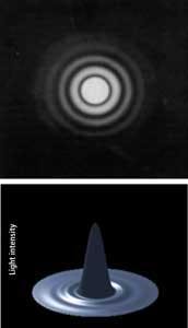
This is important since the Airy disk is the smallest point a beam of light can be focused. The disk comprises rings of light decreasing in intensity and appears similar to the rings on a bulls-eye target. The center bright spot contains approximately 84% of the total spot image energy, 91% within the outside diameter of the first ring and 94% of the energy within the outside diameter of the second ring and so on (see Fig. 1a and 1b). The Airy disk diameter (ADD) can be calculated by
The image spot size can be considered the diameter of the Airy disk, which comprises all its rings. The spot size that a lens produces has an increasingly significant role in digital imaging. This is because the individual pixel size on the latest sensors has been reduced to the point where it is comparable or smaller than the Airy disk size.
It is important to consider the Airy disk diameter at a particular f/# since the Airy disk diameter can be considerably larger than the individual pixel size. Using a lens set to f/8.0 will be performance limited by an individual pixel size <12.35 µm (see Table 1). In the table, all the values are given using a 632.8-nm wavelength.
null
Sensor resolution
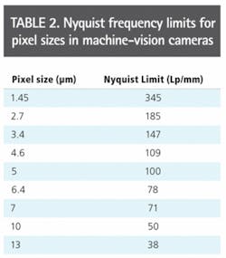
While the diffraction limit in line pairs/mm determines the resolving power of the lens, the resolution limit of the image sensor, commonly referred to as the Nyquist frequency (NF), is also expressed in terms of line pairs/mm where
Table 2 shows the Nyquist frequency limits for pixel sizes now available in machine-vision cameras. What is required is a lens system with a fairly low f/# to even theoretically achieve the sensor limited resolution. It is common practice for such lenses to be calibrated with f/#s relating to infinity.
As an object is viewed at a finite distance in most machine-vision systems, these f/#s are no longer valid. A new “finite” f/# value must be calculated and employed on all system calculations such as spot size and resolution limits. A simple way to calculate the “finite” f/# (ff/#) is
Using the above equation, and assuming a unity optical magnification of 1, the ff/# for the lens is twice the infinity f/# value. Thus, as a rule of thumb, a lens listed with an f/# of 1.4 can be estimated to have an f/# of 2.8 when used in a machine-vision systems. Smaller and smaller pixel sizes force lenses to run at very low f/#s to theoretically achieve the resolutions limits of the sensor.
As the f/# gets lower and lower, it become more difficult to design and manufacture lenses that approach the theoretical limit. While some lens designs can approach theoretical limits, once manufacturing tolerances, different wavelength ranges, sensor alignment, microlenses, different lens mounts, and the desire to use these lenses over a range of working distances are taken into account, it becomes nearly impossible to approach the limits.
Lens design
When designing lenses, optical engineers take into account many different factors to achieve the desired resolution. In any lens design, whether for a web camera or for a high-resolution imaging system, the lens performance varies with the working distance, ff/#, or the wavelength range.
Each lens has a sweet spot where the best performance is obtained. As factors such as working distance are varied, system performance fall-off will occur. The higher the resolution of the system, the faster this will happen.
In the case of Sony’s 5-Mpixel sensor that features 3.45-µm pixels, for example, sensor-limited resolution really cannot be achieved even theoretically both at very short working distances and at longer working distances with the same lens. Thus, it is critical to discuss with lens manufacturers what the working distance for a specific application will be and to understand how the lens will perform at that distance.
Any lens product cannot be used to make such systems work effectively. Remember: A lens is not guaranteed to perform in a 5-Mpixel camera simply because it is specified as a 5-Mpixel lens.
In the past, machine-vision systems used lenses developed for microscopy, photography, and security applications. While these lenses can be very good, they do not maximize the capabilities of imagers used in machine vision. Additionally, the high level of price pressures in these markets requires loosened manufacturing tolerances and such lenses may omit the features of those specifically designed for machine vision.
Tighter tolerances
The tighter the tolerance of the manufacturing process, the more closely the lens will achieve the parameters of an ideal design. Tighter manufacturing tolerances also lead to a more repeatable lens—important when installing multiple systems—and better image quality across the entire sensor. Because image quality generally falls off at the corner of the image first, loosening tolerances only enhances and in many cases accelerates these effects.
System developers do not require a background in optical mechanical design to determine if lens tolerances are tight enough. However, it should be determined whether the design information is for the ideal/nominal design or for the tolerance design. Since many lenses are specified using tolerance design information, the lens vendor may need to provide test images set for a specific application requirement.
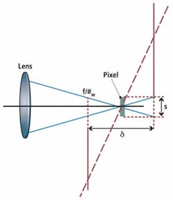
The higher the resolution of the system, the lower the f/#needs to be to resolve spots small enough to match the camera’s resolution. The lower the f/# of the lens, the larger the cone of light for a specific distance that the lens is working in, and the faster rays will diverge before and after best focus. If the alignment of the lens to the sensor is not tight enough, even a lens that meets specific resolution requirements may not yield a system that meets specification.
Figure 2 shows a sensor (in red) tipped in relation to the lens system where the dashes represent individual pixels. The solid red line (right) indicates the point at which the defocusing of the cones of light produced by the lens grows larger than the pixels, creating out-of-focus imaging beyond those points. If enough pixels are added and the alignment is not perfect, the system will become defocused.
Asking a camera manufacturer how they guarantee the alignment of their sensor with relation to the camera lens mount is the best way to reduce the risks associated with this issue. Higher levels of alignment do add cost, but performance is maximized. For high levels of pixel density in linescan and 11-Mpixel and 16-Mpixel cameras, alignment tools may be designed into the lens or camera.
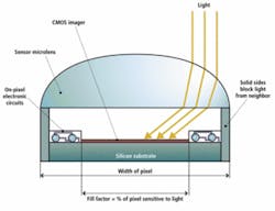
Increasing fill factor
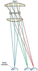
Microlenses increase the fill factor of the sensor by capturing as much light as possible. However, like any lenses they have an acceptance angle at which they will still effectively collect light and focus it onto the active portion of the pixel (see Fig. 3). If the external lens used to form an image on sensors that use microlenses exceeds this angle, then the light does not reach the sensor (see Fig. 4).
As sensors grow larger and larger, the acceptance angles of each of these microlenses do not change. The angle of light from the center of the external lens to the pixels farther and farther from the center of the sensor does change, as can be seen by the green and red ray traces of Fig. 4.
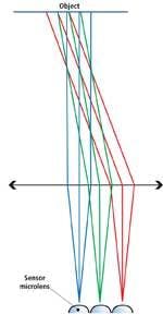
As sensor resolutions increase, light must still reach individual microlenses on the sensor at angles as low as 7° so that shading or roll-off does not occur. To overcome this, lens manufacturers such as Schneider Optics and Edmund Optics will be offering external lenses that are near telecentric in image space. In such designs, the angle of light farther and farther from the center will remain on-axis and no angular roll-off will occur (see Fig. 5).
Many have enjoyed the advances in sensor development associated with consumer cameras, but products designed for consumer applications and those for machine vision are vastly different. There will always be overlap and commonality between these areas, but understanding machine-vision optics is mandatory for those building high-resolution imaging systems.
Greg Hollows is director, machine vision solutions, at Edmund Optics, Barrington, NJ, USA; www.edmundoptics.com; and Stuart Singer is vice president of Schneider Optics, Hauppauge, NY, USA; www.schneideroptics.com.