Choosing a line scan camera for web inspection applications
Developers can choose from a range of line scan cameras each with their own price/performance tradeoffs.
Whether it is for sheet metal analysis, food inspection or 3D imaging applications, line scan cameras are offered with numerous disparate sensors, speeds and interfaces. With grey-scale, color or time-delay integration (TDI) sensors, systems developers can choose from a number of line scan cameras to best fit their applications.
Unlike area array cameras that employ sensors with two-dimensional pixel arrays, line scan cameras employ single, (e.g. 2048 x 1) or multiple rows of pixels (e.g. 2048 x 2) to capture images as objects or the camera moves across the field of view of the lens. In area array cameras, the achievable resolution is limited by the pixel size and the resolving power of the lens. In line scan cameras, this resolution is specified in the horizontal axis since the achievable resolution in the vertical direction will depend on the clock rate of the camera and the speed of the web. Line scan cameras are also easier to correct for DSNU, PRNU, lens shade and distortion as only a one-dimensional correction has to be applied and the calibration data is only required for one line. However, line scan cameras require a lot more light as the exposure time is a lot shorter than for area scan cameras. Thus, specific high intensity line light sources have been developed for line scan applications.
Image sensors
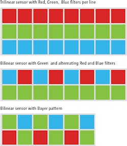
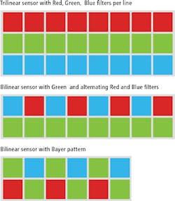
Line scan cameras exist with different image sensors that are offered in both monochrome and color configurations (Figure 1). In single-line monochrome line scan cameras, a linear sensor consisting of multiple pixels (e.g. 2k) in a x 1 configuration are used. To obtain a color image from single-line scan imagers, a linear R-G-B-R-G-B filter is applied to the sensor and the pixels that are sequentially read from the device combined to generate a color image. As with color area array cameras, this results in an interpolated image with lower resolution.
There are, of course, other methods line scan camera vendors employ to capture color images. Using a dual-line image sensor, for example, the Bayer pattern can be replicated. This is the approach taken by Basler (Ahrensburg, Germany; www.baslerweb.com) in its sprint series of line scan cameras. With up to 140kHz line rate using 2k or 4k dual-line image sensors or 70 kHz with a 8k dual-line image sensor, the sprint series support the Camera Link interface. This is the same approach taken by Aphesa (Harze, Belgium; www.aphesa.com) in its FlEye, a series of cameras that use line scan sensors from Awaiba (Nürnberg, Germany; www.awaiba.com).
To reduce spectral cross talk, many color-line scan cameras use an R-B-R-B-R-B filter on the first line and a green filter on the second line. In its Piranha P4-8k, 8k dual line Camera Link line scan camera, Teledyne DALSA (Waterloo, ON, Canada; www.teledynedalsa.com) has placed the R and B channels are placed next to each other because they have less spectral overlap. Alternatively, a tri-linear sensor can be employed where a single color R, G or B filter is applied on each line of pixels. Here again, Teledyne DALSA offers a number of Piranha line-san cameras that use tri-linear sensors.
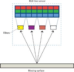
Tri-linear sensors can also be used to build multispectral line scan cameras such as the truePIXA camera from Chromasens (Konstanz, Germany; www.chromasens.de). In the design, four lenses in front of the sensor each project an image onto a separate part of the RGB line sensor and are oriented to provide the same FOV. By placing different filters in front of the lenses, the spectral responsivity of the RGB line sensor can be changed (Figure 2). Evaluation of the camera has recently been performed at the Institute of Printing Science and Technology, Technische Universität Darmstadt (Darmstadt, Germany; www.tu-darmstadt.de) - see "Evaluation of a multi- spectral camera system for inline color measurement" http://bit.ly/1RxMzAj).
To obtain the best color reproduction in their line scan cameras, three separate monochrome linear sensors can also be used. Using a prism, the incoming light is then separated optically into RGB components and captured by each individual image sensor. This is the approach taken by JAI (San Jose, CA, USA; www.jai.com) in its LQ-200 Camera Link line scan camera. Instead of using three image sensors to capture color images, the camera uses four 2048 x 1 line-sensors mounted on an RGB/NIR beam splitter prism. R, G, B and NIR light spectrum bands are captured simultaneously in four separate channels through the same optical path. Adding an NIR channel makes the camera suitable for such applications as fruit and vegetable sorting since captured image data can be used to identify a larger number of defects than with color image data alone.
Faster speeds
Scan frequencies of line scan cameras are specified at kHz rates, a number that can be calculated by dividing the camera clock rate by the number of pixels in the imager. Thus, for a camera that employs a single tap 2048 x 1 line scan imager and uses a 40MHz data clock rate, the scan frequency will be 40MHz/2048 or 19.5kHz or 19,500 lines/s of data.
While cross-web or horizontal resolution depends on the pixel sizes used in the imager and the optics used, the vertical down-web resolution is dependent on the camera optics, clock rate and speed of the web. For a line scan camera with 10-μm square pixels, for example, the maximum achievable resolution in the horizontal direction using a lens with 1:1 magnification is theoretically 20μm according to Nyquist criteria (although this is practically unachievable). By using a clock rate of 19.5kHz, imaging a web with a speed of 1m/s will produce a down-web resolution of 51.28μm and result in asymmetrical 20 x 51.28μm pixels. Obviously, in such an application, a faster line scan frequency would be required.
In machine vision applications, it is essential that the line scan sensor employs square pixels and that the camera will produces square pixels in both the horizontal and vertical directions. This ensures that the image of the scanned object will be vertically and horizontally proportional. This necessitates the use of an incremental encoder to track the web speed (or camera motion) as it moves across the field of view of the object. This is used to dynamically adjust the camera's line rate during image acquisition.
If the web moves more slowly, the line rate can be reduced and vice versa ensuring the same down-web resolution irrespective of web speed. However, reducing or increasing the camera line rate directly increases or reduces the camera exposure time, resulting in brighter or darker images being captured. To compensate for this, the exposure time of the sensor must be automatically adjusted regardless of the camera line rate.
More taps
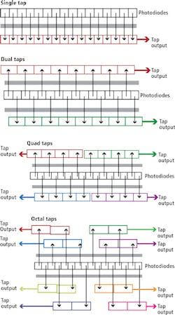
Many applications require faster speeds than can be obtained with single tap line scan cameras. To increase this speed, sensors that employ dual, quad and octal taps can be used (Figure 3). While single-tap sensors shift the signal from the imager through a single output, dual-tap configurations shift the signal from each alternating pixel site in the linear array into two even and odd outputs, effectively doubling the scan frequency of the camera. Another version of this dual tap design shifts the first half of the linear array of pixels through a single output while a second tap is used for the second half of pixels on the array. In higher performance line scan cameras, quad and octal taps are used to further increase performance by four and eight times, respectively.
While web inspection systems require line scan cameras to operate at high scan rates, they also demand that the images captured are of high-contrast. Especially when used in light-starved applications, the sensitivity of cameras-based on single x 1 linear image sensors may not be sufficient. To increase this sensitivity, multi-line scan cameras can be employed.
In dual-line scan designs, two parallel arrays of photodiode pixels are used to capture twice the number of photons. By combining the signal from adjacent photosites, the sensitivity is doubled. Such cameras areoffered by a number of companies including Teledyne DALSA and Aphesa. In its Spyder3 family of dual-line scan cameras, Teledyne DALSA offers a number of different cameras that employ sensors with 1024 x 2 to 4096 x 2 pixel formats in both Camera Link and GigE configurations.
Rather than use two parallel arrays of photodiodes, the sensor used in the Eliixa+8k line scan camera from e2v (Chelmsford, England; www.e2v.com) is composed of two pairs of photodiode arrays in an 8192 x 4 configuration. In one of the cameras multi-line modes, the camera can be configured to sum each of the four pixels in both pairs of lines to increase the sensitivity of the Camera Link camera.
Time delay
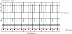
This concept has been further extended in line scan cameras based on time-delay integration (TDI) where a number of integration stages are used to further increase sensitivity. Unlike cameras that employ-single line image sensors where each line captured is transferred to a single or multiple read-out registers, TDI-based line scan cameras employ a number of vertical integration stages (Figure 4).
In operation, these vertical integration stages are used to capture multiple exposures of the same object as it moves in the down-web direction. By using multiple stages and integrating the output from these stages, sensitivity is increased. Here, the amount of increased sensitivity will be dependent on the number of integration stages. Today, a number of variations of these cameras exist with sensors offered in such configurations as 4096 x 48, 8192 x 96 and 17824 x 256.
In its latest VT Series of line scan cameras, Vieworks (Anyang-si, Gyeonggi-do, Korea; www.vieworks.com), for example, offers a number of different TDI sensor configurations ranging from 4096 x 128 to 17824 x 256 with both Camera Link and CoaXPress (CXP) interfaces. The company's VT-18KX-H 80, for example, supports the 256 TDI stage and a 17825 imager with a line rate of 80kHz and a CXP interface.
Companies mentioned
ADLINK Technology
New Taipei City, Taiwan
www.adlinktech.com
Aphesa
Harze, Belgium
www.aphesa.com
Awaiba
Nürnberg, Germany
www.awaiba.com
Basler
Ahrensburg, Germany
www.baslerweb.com
Chromasens
Konstanz, Germany
www.chromasens.de
e2v
Chelmsford, England
www.e2v.com
JAI
San Jose, CA, USA
www.jai.com
NET
Finning, Germany
http://net-gmbh.com
Schäfter + Kirchhoff
Hamburg, Germany
www.sukhamburg.com
Stemmer Imaging
Puchheim, Germany
www.stemmer-imaging.de
Technische Universität Darmstadt
Darmstadt, Germany
www.tu-darmstadt.de
Teledyne DALSA
Waterloo, ON, Canada
www.teledynedalsa.com
Vieworks
Anyang-si, Gyeonggi-do, Korea
www.vieworks.com
Xenics
Leuven, Belgium
www.xenics.com
For more information about line scan cameras and sensors, visit Vision Systems Design's Buyer's Guide: buyersguide.vision-systems.com
Line-scan imaging on the web
Line-scan imaging basics - Teledyne DALSA
http://bit.ly/1LA5Dw9
Tri-linear cameras offer high-speed color imaging solutions - Stemmer Imaging
http://bit.ly/1kNjS89
PC-based line-scan imaging systems - ADLINK Technology
http://bit.ly/1NyHl6t
Evaluation of a multi-spectral camera system for inline color measurement - Technische Universität Darmstadt
http://bit.ly/1RxMzAj
Dual Line Scan: Make Mine a Double -Teledyne DALSA
http://bit.ly/1idWrD5
Various line-scan configurations - NET
http://bit.ly/1LA67Tb
SWIR line-scan cameras - Xenics
http://bit.ly/1O5ydJJ
Introduction to line scan cameras - Schäfter + Kirchhoff
http://bit.ly/1OVDrrE
About the Author

Andy Wilson
Founding Editor
Founding editor of Vision Systems Design. Industry authority and author of thousands of technical articles on image processing, machine vision, and computer science.
B.Sc., Warwick University
Tel: 603-891-9115
Fax: 603-891-9297
