Product Focus: Cabling choices for camera interfaces
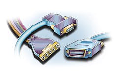
With the numerous camera-to-computer interfaces standards now available, systems integrators can choose from a range of cabling options.
At first glance, specifying which cables and connectors to interface cameras to computer systems may appear an easy task. However, although the task of choosing which cable and connector to use may be relegated as an afterthought after the selection of cameras, lighting and software, it should not be. Indeed, by correctly specifying the different types of connectors and cables for the numerous machine vision standards now available, systems developers can more effectively implement their machine vision systems.
Choosing which types of cables and connects to use is dependent of the type of camera to computer interface. Today, many different digital standards exist of which the most popular are Camera Link, Camera Link HS, CoaXPress (CXP), GigE Vision and USB3 Vision.
To compare these standards and the camera-to-computer cable distances that are specified for each one, the AIA (Ann Arbor, MI, USA;www.visiononline.org), the European Machine Vision Association (EMVA; Barcelona, Spain; www.emva.org), and Japan Industrial Imaging Association (JIIA; Tokyo, Japan) have collaborated and prepared a 24-page brochure entitled "Global Machine Vision Interface Standards" that can be downloaded from each of the association's websites. The brochure is available in English, Japanese and Chinese.
With the emergence of active electrical cables, active electrical/optical cables, and active repeaters, cables and peripherals, manufacturers have extended many of the specified camera to cable distances specified in each of these standards (see "Clearing Up Choices for Cabling and Connectors,"Vision Systems Design, September 2012; http://bit.ly/1Sx9bR5). This allows systems integrators to more easily specify a number of different types of camera interfaces without necessarily having to be concerned with camera-to-cable distance limitations.
While Camera Link, Camera Link HS, CoaXPress (CXP), GigE Vision and USB3 Vision are now established standards, the chairmen of the technical committees that oversee each one are each working on ways to improve them. In a recent webcast entitled "How the newest machine vision standards will affect you," Bob McCurrach, Director of Standards Development at the AIA introduced members of each of these working groups with the aim of highlighting the latest developments (http://bit.ly/1ebsMIU).
Camera Link and beyond
As one of the most well-established camera interfaces, the now over 15-year-old Camera Link standard has evolved to support mini-Camera Link connectors for small form factor cameras and Power over Camera link (PoCL) to reduce the amount of system's cabling required. Originally implemented with discrete transceivers from National Semiconductor (Coppell, TX, USA;www.national.com), many camera and frame grabber companies now implement these transceivers as part of their FPGA designs.
"While this results in cost and space savings, a formalized version of the FPGA core to perform this function will ensure a consistent performance across the interface," says Steve Kinney, Chair of the Camera Link Committee and General Manager of Business Development at CCS America (Burlington, MA, USA;www.ccsamerica.com). To test these various FPGA configurations, the Camera Link committee is also working on a test program that uses a linear feedback shift register to generate a deterministic sequence of test patterns between the camera and frame grabber.
"By using this test sequence," says Kinney, "it will be possible to develop a standard method for validating Camera Link cables and test the FPGA implementations used for the Camera Link interface."
As the next generation Camera Link interface, Camera Link HS was introduced in 2012 to improve cable length and bandwidth while adding the general purpose I/O and data reliability features missing in the original Camera Link standard.
"Currently, there are two shared IP cores available from the AIA that support each of the physical layer implementations of the Camera Link HS standard," says Mike Miethig, Chair of the Camera Link HS Subcommittee and R&D Camera Development Manager at Teledyne DALSA (Waterloo, ON, Canada;www.teledynedalsa.com). While the M core currently supports 3.125 Gbits/s per lane and is designed for implementation in low-cost FPGAs, the X protocol supports speeds of 10.3 Gbits/s per lane.
Using a single CX4 cable, up to seven data lanes and one command channel is supported by the M core while a single data lane and command channel is available when using an SFP+ connection. In the future, data speed per lane using the M protocol will be increased to 6.25Gbps/lane using the SFP+ connector and to 5Gbps using the CX4 connector. "Copper CX4 cables can be purchased from many machine vision cable suppliers," says Miethig, "including those with a 5 million cycle flex-life from Hirakawa Hewtech (Shinagawa, Tokyo, Japan;www.hewtech.co.jp)."
CLHS allows up to eight cables from the camera. While the X protocol currently specifies the use of a SFP+ connector resulting in a single bidirectional channel of 10.3Gbps, using a Quad Small Form-factor Pluggable (QSFP) connector will enable X protocol Camera Link HS systems to support four channels of data, allowing a fourfold data throughput over a single fiber cable.
CXP innovation
At the same time the Camera Link HS standard was being developed, a consortium of companies including Active Silicon (Iver, England;www.activesilicon.com) was underway developing the CoaXPress (CXP) standard. The CXP standard allows a single coaxial cable to provide up to 6.25Gbps image data and camera power and control signals between the frame grabber and camera at distances of < 50m at these data rates and 100m at 3.125Gbps. To increase this speed, multiple cables can be used.
In Version 1.0 of the standard, multiple BNC cables were used. According to Chris Beynon, co-chair of the CoaXPress Committee and Chief Technical Officer of Active Silicon, Version 1.1 of the standard allows smaller DIN connectors to be used. "The benefit to this DIN connector is that it can be used to manufacture cables with multiple coax cores," he says. Thus, one cable containing five CXP coax can be used to provide 25Gbps for camera data and 6.25Gps for camera control.
Developers interested in developing CXP-based cameras and frame grabbers can also purchase IP from a number of vendors such as Mercury Systems (Chelmsford, MA, USA;www.mrcy.com), Sensor to Image (Schongau, Germany; www.sensor-to-image.de) and Kaya Instruments (Haifa, Israel; www.kayainstruments.com) with which to implement the data and control protocols specified in the CXP standard.
In the future, the CXP standard will be extended to support speeds of 10Gbps (CXP-10) and 12.5Gbps (CXP-12). Thus, a single six-core CXP-12 will support data rates of up to 7.5GBytes/s, nearly an order of magnitude faster than Camera Link Deca. "Because this may be faster than the PC can handle," says Beynon, "the CXP Committee is adding support to connect cameras to multiple frame grabbers, even if they are located in different PCs."
Extending established standards
While the Camera Link, Camera Link HS and CXP standards were developed specifically for the machine vision market, GigE Vision and USB3 Vision standards leverage from established computer-based interfaces while adding functionality required by developers of imaging systems.
Like the Gigabit Ethernet standard, the GigE Vision 2.0 standard can use any of the physical layers that Ethernet will support including CAT-5e cables of up 100m in length, 10Gigabit Ethernet cables and Gigabit Ethernet fiber-optic cables.
Rather than use connector cables with plastic clips, the GigE Vision standard adds locking screws to the connector to increase robustness. Cable companies offering the GigE Vision locking connector include Alysium Tech (Nuremberg, Germany;www.alysium-tech.com), Components Express (Woodridge, IL, USA; www.componentsexpress.com), Intercon 1 (Merrifield, MN, USA www.intercon-1.com) and Newnex (Santa Clara, CA, USA; www.newnex.com). "These companies are members of the GigE Vision committee and are helping to define the form factor of the copper locking cable," says Eric Carey, Chair of the GigE Vision Committee and Program Director, Areascan Machine Vision at Teledyne DALSA.
Version 2.1 of the standard will introduce a formal version of the locking connector to ensure interoperability between cameras and frame grabbers. "Possible future directions include support for NBASE-T and a smaller connector that will provide useful for manufacturers of smaller sized cameras," says Carey.
USB3 Vision also leverages a well-established standard. Released over two years ago, the standard adds to the functionality of the original standards with features developed specifically for machine vision systems. Like USB 3.0, the cables and connectors employ a Type A (Host) connector and a Type B (Device) connector. "From the beginning the standard defined standard locking connectors for industrial machine vision applications," says Eric Gross, Chair of the USB3 Vision Committee and Senior Software Engineer at National Instruments (Austin, TX, USA;www.ni.com).
While the current version of the standard only supports these connectors, a future version of the standard will likely include support for an industrial version of the USB Type C connector. "One of the key advantages of the Type C connector is that is smaller than the current Type A and Micro B connectors, making it useful for smaller cameras," says Gross.
Just as USB and Ethernet have been adopted to meet the needs of machine vision, cameras using the Thunderbolt standard, co-developed by Apple Computer (Cupertino, CA, USA;www.apple.com) and Intel (Santa Clara, CA, USA; www.intel.com) were shown by Allied Vision (Stadtroda, Germany; www.alliedvision.com) and XIMEA (Munich, Germany; www.ximea.com) at last year's VISION 2014 tradeshow in Stuttgart (see "Camera vendors introduce Thunderbolt products at VISION 2014," Vision Systems Design, January 2015; http://bit.ly/1MKgZgu).
At present, however, other vendors have been reluctant to adopt this standard. "At the moment we do not feel there is a critical mass for this," says Bob McCurrach, "although the AIA will be monitoring the future developments of the Thunderbolt standard as they occur."
Companies mentioned
Active Silicon
Iver, England
www.activesilicon.com
AIA
Ann Arbor, MI, USA
www.visiononline.org
Allied Vision
Stadtroda, Germany
www.alliedvision.com
Alysium
Nuremberg, Germany
www.alysium-tech.com
Apple Computer
Cupertino, CA, USA
www.apple.com
CCS America
Burlington, MA, USA
www.ccsamerica.com
Components Express
Woodridge, IL, USA
www.componentsexpress.com
Hirakawa Hewtech
Shinagawa, Tokyo, Japan
www.hewtech.co.jp
Intel
Santa Clara, CA, USA
www.intel.com
Intercon 1
Merrifield, MN, USA
www.intercon-1.com
Kaya Instruments
Haifa, Israel
www.kayainstruments.com
Mercury Systems
Chelmsford, MA, USA
www.mrcy.com
National Instruments
Austin, TX, USA
www.ni.com
National Semiconductor
Coppell, TX, USA
www.national.com
Newnex
Santa Clara, CA
www.newnex.com
Sensor to Image
Schongau, Germany
www.sensor-to-image.de
Teledyne DALSA
Waterloo, ON, Canada
www.teledynedalsa.com
XIMEA
Munich, Germany
www.ximea.com
About the Author

Andy Wilson
Founding Editor
Founding editor of Vision Systems Design. Industry authority and author of thousands of technical articles on image processing, machine vision, and computer science.
B.Sc., Warwick University
Tel: 603-891-9115
Fax: 603-891-9297


