Vision system guides incoming aircraft
In all weather conditions, a docking system gives pilots guidance to the gate.
By R. Winn Hardin, Contributing Editor
In perfect weather, when the sun is shining and the skies are clear, a commercial airline pilot can park an airplane within 1 m of the disembarkation point, where a motorized bridge can connect properly with the passenger exit door 99 out of 100 times. However, at nighttime or in fog, rain, or snow, the usual markers and visual points a pilot or ground marshal uses to manually guide an aircraft to the disembarkation point are difficult to spot.
Using algorithms originally developed at the Fraunhofer Gesellschaft (Munich, Germany), Honeywell Airport Systems GmbH (Wiedel, Germany) has developed its Visual Guided Docking System (VGDS). Installed at airports in Germany, China, and Korea, the system includes a high-dynamic-range CMOS camera to collect images of incoming aircraft, a Sun Microsystems (Santa Clara, CA, USA) UltraSparc II workstation to process the image of the incoming aircraft and communicate with the flight information system (FIS) and airport operations database (AOD), and a wall-mounted, oversized LCD to give the pilot directions and distance for parking the plane at the proper disembarkation point.
A welding lesson
According to Helmut Hengvoss, head of business development for Honeywell Airport Systems' German division, the VGDS uses a proprietary 512 × 256-pixel CMOS camera that was modified from a camera specifically designed for automated welding applications. Honeywell chose the sensor because, as in welding applications, the VGDS sensor needed to be sensitive to light, so it can see at night or in inclement weather, such as fog, without special lighting, while having the dynamic range to handle reflection from snow and metal.
"The camera has a very wide contrast and dynamic range that is not comparable to consumer and other industrial cameras," Hengvoss said. The camera/lens combination offers an aircraft recognition and guidance range between 20 and 100 m and an accuracy of ±0.2 m lateral and ±0.5 m longitude.
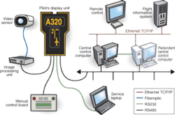
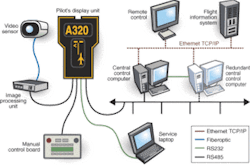
The camera connects via Fibre Channel cable connection to the image-processing unit, a Sun Microsystems SPARC engine Ultra2 dual 200-MHz processor, Linux-based workstation with 256 Mbytes and large internal hard drive, typically mounted on the embarkation ramp to protect it from the elements. A custom manual-control board from Honeywell acts as the VGDS control panel for ground personnel and communicates with the SPARC workstation via RS 485 cable and a Motorola (Schaumburg, IL, USA) MC68302 single-chip communication processor/gateway board located in the pilot display unit, which can be mounted on the wall of the airport or on a pole facing the incoming aircraft and in the pilot's line of sight. The MC68302 acts as the communication gateway between the VGDS at the gate and a central workstation and can be easily programmed to meet communication protocols such as Fibre Channel, Ethernet, or RS232 (see Fig. 1).
The central workstation, which can be either a less-powerful SPARC workstation or desktop PC, acts as a communication hub for up to 280 VGDSs, as well as an interface between the VGDSs and the airport data networks and databases, including the FIS and AOD. The FIS tracks aircraft flight schedules, while the AOD provides traffic control on the ground. This central hub can also control an optional video switch bar that allows any VGDS to view the video coming from any other VGDS, providing an additional layer of CCTV-type security for the airport apron.
"We have created a modular system using object-oriented software so we can shift from hardware to hardware as long as it's a UNIX- or Linux-based system. Explained Hengvoss, " If you use a operating system such as Windows you have to adapt it every two years to the latest version. With UNIX, we're free for the next decade."
The central hub workstation takes the incoming flight data and transmits them across the existing data network at the airport (fiber or copper) through a TCP/IP protocol on RS485 industrial control network to the MC68302 communications gateway and to the VGDS image-processing workstation at the gate. RS485 provides less bandwidth than standard Ethernet at 2.5 Mbits/s, but can accommodate longer runs without repeater boxes of up to 1200 m. The system can also display textual information for the pilot.
"We need horsepower for this application," commented Hengvoss on the decision to go with a SPARC dual-processor workstation. Using the airplane description from the FIS, the VGDS retrieves a digital, 3-D model of that aircraft type from its hard drive, based on publicly available schematics for each airplane model. A 2-D pattern is created from the 3-D model by rotating the model to reflect the orientation of the incoming aircraft based on previous measurements related to the tarmac surface.
The model is then flattened into a 2-D pattern using optical-design ray-tracing techniques. First, a number of algorithms, including thresholding and edge detection, identify the "real" aircraft within the frames that make up the incoming video feed. The 2-D rendering of the 3-D model is then pattern-matched to the region of interest in the incoming video frames that represent the airplane. By using pattern matching to compare the 2-D image to the incoming video, the VGDS reduces the negative effects of rotation and scale.
At this point, the VGDS either matches the 2-D pattern to the incoming images of an approaching airplane and automatically guides the it along the centerline through directional commands on the pilot display unit, or conclusively determines that the approaching aircraft is of the wrong type. In this case, the VGDS displays an error notice on the display to stop the docking and sends a similar signal to the airport operations database.
After the aircraft has been confirmed as the proper model, the system uses the model as a pattern to track the movements of the aircraft within the acquired images. It conveys distance information based on its scale and position within the image and known locations on the apron programmed during initial system setup and calibration.
Initial calibration of the system is important for efficient scaling and comparison of the model, Hengvoss said. During system setup, a technician using a laptop and RS232 connection programs the VGDS with the expected aircraft types for that gate. Also a special reflector is moved periodically along the painted guideline that shows the optimal approach angle for the aircraft. By taking multiple readings along the camera depth of field, the system can handle straight or curved painted guidelines in the docking tarmac and guide the pilot based on aircraft type.
Range data and a 'left' or 'right' graphic display of the aircraft and centerline are sent from the VGDS image-processing workstation to the MC68302 controller and relayed across an RS485 connection to a custom-made pilot display unit that includes three separate transreflecting liquid-crystal displays. Transreflecting displays provide an easily readable picture, even under direct sunlight, according to Hengvoss. Range and position data are updated on a per-meter basis and in 20-cm increments within the last meter to allow the pilot to come to an easy stop at the disembarkation point (see Fig. 2).
Unlike other systems on the market, Hengvoss said, the VDGS is not based on visual alignment indicators that are positioned specifically for the pilot seated on the lefthand side of the airplane. "If you make the system so both the pilot and copilot can read it together, the margin of error drops to one in 10,000." Therefore the actual standards ask for systems that can be used by both pilot and copilot.
features, advantanges, benefits
Brussels National Airport (BNA) operations director May Schrauwen was looking for a method to automate aircraft guidance after landing. Following an extensive search, she selected Honeywell Aircraft Systems Visual Guided DockingSystem (VGDS) for 57 docking stations, including 37 at the main pier and 20 at remote locations around the airport.
"The system is working quite well," says Schrauwen. "We had some small problems in the beginning, since it's a rather demanding system." She adds that BNA has tied the VGDS directly into the flight information system, fully automating aircraft traffic in and around the airport.
"It's a standardized system that works the same wherever it's used, and that's what the pilots like," she says, adding that the only improvement to the system that she would like to see is an increased number of available templates. "Sometimes with very small planes, a template may not be available, and having a template made can be expensive."
Company Info
Fraunhofer Gesellschaft www.fraunhofer.de
Honeywell Airport Systems GmbH airportsystems.honeywell.com/
Motorola www.motorola.com/
Sun Microsystems www.sun.com


