Camera Link standard advances interfacing
Version 1.1 of the Camera Link standard attempts to specify improved serial communication and configuration, smaller connectors, and product compliance.
By Andrew Wilson, Editor
It has been more than two years since the first Camera Link interface specification was published by the Camera Link Committee, which is made up of representatives from camera and frame-grabber companies. During this time, more than 70 companies have introduced Camera Link-compatible products that include cameras, frame grabbers, connectors, fiberoptic adapters, and interfaces (see Vision Systems Design, January 2003, p. S4).
Supporting Base, Medium, and Full configurations, the Camera Link standard offers systems integrators an easy way to reduce the bulky cabling and large-size connectors associated with previous low-voltage-differential-signal (LVDS) designs. Understanding these benefits, nearly every major camera vendor now offers products that support the Camera Link standard in one form or another (see table).
In 2002, the Automated Imaging Association (AIA; Ann Arbor, MI, USA) took over ownership of the Camera Link standard. It plans to unveil the latest version of the specification—Revision 1.1—at this year's International Robots & Vision Show (Rosemont, IL; June 3 to 5). What is, perhaps, most important about the proposed revision of the Camera Link specification is what is not included rather than what is.
Look to the past
Two years ago, Mike Miethig, technical manager with the camera research-and-development department at Dalsa (Waterloo, ON, Canada), published the Dalsa Camera Link Implementation Road Map, a voluminous document that described the interfacing work yet to be accomplished (vfm.dalsa.com/support/appnotes/00450-00_03-32_dalsa_camera_link_road_map.pdf). This document included the fact that no formal mechanisms are yet in place to verify the compliance of Camera Link products and that there is no automatic camera/frame-grabber configuration capability allowing true "plug-and-play" product integration. Moreover, it proposed a method for formatting output data in several ways to broaden the choice of frame grabbers that support specific cameras.
"Dalsa's document was developed independently of the Camera Link Standard and is one company's vision for its Camera Link products. It has not been presented to the Camera Link Committee and is not a representation of the committee's roadmap for this standard," points out Stefanie Breyer, R&D senior group manager of the machine-vision group at National Instruments (Austin, TX, USA) and vice chairperson of the Camera Link Committee. "In the Camera Link standard," says Breyer, "two LVDS signal pairs are used for asynchronous serial communications between the camera and the frame grabber." A differential pair named as serial-to-frame grabber (SerTFG) provides serial communications output from the camera to the frame grabber. Similarly, the second differential pair, called serial-to-camera (SerTC), is used to communicate between the frame grabber and the camera.
"Although the standard defined a hardware-based means of communication," says Breyer, "each frame-grabber vendor, such as National Instruments, provided a vendor-specific application programming interface (API) for programming and communicating over the frame grabber's serial port. Camera companies were forced to write individual software programs to control cameras functions for each frame grabber that they wanted to support," she adds. The National Instruments NI PCI-1428 PCI-based frame grabber supports both Base and some Medium Camera Link configurations, and the company currently supports a range of cameras from companies such as Adimec (Eindhoven, The Netherlands), Basler (Ahrensburg, Germany), Cohu (San Diego, CA, USA), and Dalsa, as well as 16 others.
Supported cameras
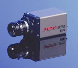
The Adimec 1000m and Cohu 7500 cameras are supported by National Instruments and several other Camera Link frame-grabber manufacturers. While both cameras are Camera Link compliant, they differ significantly in their technical specifications. The Adimec 1000m camera is a 1004 × 1004-pixel camera that runs at up to 50 progressive frames/s at full resolution via the Camera Link interface (see Fig. 1). With the camera's partial-scan read-out mode, programmable images with full horizontal resolution can be obtained at a higher frame rate.

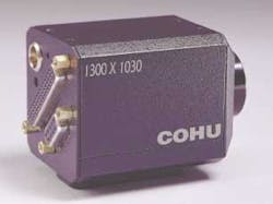
The Cohu 7500 camera can be operated in several different modes, including a progressive-scan (noninterlaced) mode for a 1300 × 1030-pixel image at 12 frames/s or half-line resolution at 24 frames/s through a 10-bit digital output or a Camera Link connection (see Fig. 2). The camera's shutter can operate in different modes and at selectable speeds.
"In the past, to configure the different functions of these and other cameras," says Breyer, "the camera vendor needed to write a different program to support each specific frame grabber." Because of this time-consuming and often repetitive work, the Camera Link Committee is currently proposing two APIs for asynchronous serial reading and writing. Camera manufacturers will use the first API to create frame-grabber-independent camera-configuration utilities. The second API, provided by frame-grabber manufacturers, will provide manufacturer-specific information of serial communications functions.
Both APIs will provide requests for services and a means of communicating with other software that programmers use in writing applications, such as setting the camera baud rate, determining which manufacturer's camera or frame grabber is being used, and reading data from the camera or the frame grabber. Using the API, programmers can develop programs in Visual Basic or C and call functions from an import library that allows commands such as flush port and get path info to be implemented as a single command.
High-level languages
At the highest level, the camera vendor runs the developed camera application using the import library of functions. The application then calls clallserial.dll, a dynamic-link library (DLL) that provides a set of routines that are loaded and linked into the application at run time. This DLL then searches the operating system directory for any files named clserxxx.dll; DLLs must be supplied by frame-grabber companies with xxx serving as a unique identifier of the frame-grabber company.
The DLLs consist of files that specify initializing, reading, writing, and closing the serial port as defined in the Camera Link 1.1 specification. After locating these files, clallserial.dll dynamically loads and queries each one for the port name and the manufacturer's name. Because the AIA will eventually own the source code for clallserial.dll, frame-grabber manufacturers who want to comply with the new standard must first register with the AIA, who will provide them with the unique xxx identifier for their DLL.
To be compliant with the proposed Version 1.1, camera companies should rewrite their camera-control utilities using the new API. Like the callable functions used by frame-grabber manufacturers, these functions also specify functions such as initializing, reading, writing, and closing the serial port.
"With these DLLs in place," says Tony Iglesias, software engineer with the machine-vision group at National Instruments and member of the Serial Enhancements Subcommittee, "systems integrators will be guaranteed that the serial port from the Camera Link frame grabber can be used to configure the camera." For camera companies, this will ease the systems-integration task, as only one program will need to be written to interface to multiple frame grabbers. Similarly, for systems integrators and end users, the task of writing code will be dramatically reduced.
Despite these advantages, the addition of APIs to standardize the software serial interface does not guarantee plug-and play compatibility. "The new changes to the specification define the means of communication between the camera and frame grabber, but do not define the configuration command set," says Iglesias. "You can say we've invented the telephone but not the language of communication. However, now that the basic foundations are in place, they open the door for ease-of-use improvements without impacting vendors' abilities to differentiate their products and provide unique features to their customers," he adds. Therefore, while the Camera Link 1.1 standard will define a common API between camera and frame grabber, there is no guarantee that products that adhere to the standard will be plug-and-play. "However," adds Breyer, "the common API does provide a step toward that goal."
Smaller connectors
In addition to developing the soon-to-be released APIs, the Camera Link Committee is working in two other areas: specifying a smaller connector and deciding on how to certify Camera Link products. Currently, the only connector that has been approved for both frame grabbers and cameras is the MDR-26 connector offered by the 3M Electronic and Interconnection Systems Group (Bracknell, Berks, UK) and Intercon 1 (Baxter, MN, USA). Development of a smaller connector will be especially helpful to manufacturers who are now developing very-small-format cameras and to vendors who want to build frame-grabber boards that fit in small formats such as PMC mezzanine modules.
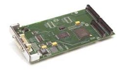
Designed for rugged implementations, the PMC form factor provides a secure mounting platform for PMC VME and Compact PCI mezzanine boards. And, while companies such as Engineering Design Team (Beaverton, OR, USA) do produce Camera Link frame-grabber boards for the PMC, the size of the connector limits the frame grabber to the Base configuration, which only requires a single connector (see Fig. 3). In such designs, the availability of a smaller connector would allow Base, Medium, and perhaps Full configurations to be supplied on a single PMC board.
Currently, there is no way for systems integrators to determine whether products that claim to be Camera Link compliant are actually compliant with the standard. To address this concern, the Camera Link Committee is considering how to provide full Camera Link certification for both frame grabbers and cameras. According to National Instruments' Breyer, this could be accomplished by a self-certification process, but may involve interoperability testing by the committee.
At the upcoming International Robots & Vision Show, the Camera Link Committee will be in session and is expected to ratify the new APIs, decide on different types of smaller Camera Link connectors, and find a means to ratify the compliance of Camera Link products. Even then, much work still needs to be done before the interface standard can be called "plug-and-play."
Company Info
Automated Imaging Association www.machinevisiononline.org
Engineering Design Team www.edt.com
Intercon 1 www.nortechsys.com
National Instruments www.ni.com
3M UK www.3m.com
Click here to download "Camera Link Cameras" pdf. {pdf size: 1,002 KB}