TRANSPORTATION - Imaging software supports container truck inspection
On any given day, thousands of trucks offload containers at ports around the world. As these trucks arrive, they must be manually inspected by authorized marine terminal operators who inspect any damage to the sides and top of the container and the presence of the container registration number located on the side/top wall. Because this process is time consuming and slows traffic flow at ports, KritiKal Solutions (Noida, Delhi, India; www.kritikalsolutions.com) has developed an imaging system based around off-the-shelf cameras and custom image-mosaicing software that speeds the inspection of the containers.
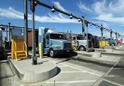
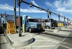
To image each truck bearing a container, an inspection was developed that consists of a goal post structure to which three cameras fitted with wide-angle lenses are mounted (see Fig. 1). While the horizontally down-facing camera is used to image the top of the container, the vertically side-facing cameras are used to capture images of the sides. Captured images are then mosaiced and presented to terminal operators for remote manual inspection.
“Of course,” says Piyush Bhargava, lead design engineer at KritiKal Solutions, “all the captured images are not required for mosaicing, making wide-angle image correction on every image an overhead.” To overcome this, background image subtraction is used to detect the start of the vehicle as it enters the inspection station. Using the background image as a reference image, normalized cross-correlation (NCC) between the reference image and the input image provides the degree of similarity (or dissimilarity) between the images. This gives an accurate measure of where the start of the vehicle appears in the sequence of captured images.
“Since wide-angle lenses provide extremely wide, hemispherical images, they will suffer from some amount of radial distortion,” says Bhargava. “Although the curvilinear images produced can be remapped to a conventional rectilinear projection, and this entails some loss of detail at the edges of the frame, the technique produces an image with a field of view greater than that of conventional rectilinear lenses.” This is particularly useful for creating panoramic images.
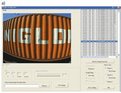
To obtain the parameters to correct for radial distortion correction for each of the three cameras, a utility called CME Configurator is used within the software. This same utility sets other parameters such as the region of interest (ROI) for each camera and specifies how intermediate results are to be saved.
The operator selects an image folder for each of the three camera views, sets the distortion correction angle manually, and visualizes the applied correction. Once these parameters are set, they are saved to the CME configuration file. Once this configuration is loaded, the wide-angle correction module performs distortion correction of each input image based on the loaded parameters.
“Registration is the most important step in image mosaicing,” says Bhargava. “This is easy due to the fixed position of the cameras and the purely translational motion of the vehicle.” A cross-correlation coefficient maximization is performed on a prespecified ROI between two consecutive grayscale down-sampled images.
This provides an accurate translational transformation between the pair of images. “Working on grayscale, down-sampled images ensures that the final image registration can happen faster,” says Bhargava. Once the images have been registered, the translational transformation is applied to the original color input images and pasted onto a bigger composite image (see Fig. 2).
FIGURE 2. a) To generate composite images of containers, wide-angle lenses capture a series of images. b) By correcting for radial distortion images are then registered and a composite image generated.
While copying the overlapping pixels, a feathering technique is used for blending. In this approach, pixel values in blended regions are generated as a weighted average from two overlapping images. Sometimes, in the presence of exposure differences, this simple approach does not work, for example. However, since all the images are captured at the same exposure using fixed cameras, this simple algorithm produces good results. A video of the system in action can be viewed at http://bit.ly/bTKdOm.
Vision Systems Articles Archives


