Linescan camera inspects stent surfaces
Balloon angioplasty provides cardiologists with a means to treat blockages of the arteries caused by coronary heart disease. To perform the procedure, cardiologists insert a long, thin tube with a balloon-tipped catheter into the artery. After the catheter reaches the blocked artery, the balloon is inflated, pushing any plaque against the artery wall. Because the artery wall may become weakened by the procedure, a small metal tube or stent is used to stop any reblocking of the artery.
“These stents are composed of expandable wire forms or perforated tubes that are often coated with a drug to prevent restenosis,” says Markus Tarin, president and CEO of MoviMED (Irvine, CA, USA; www.movimed.com). While these so-called drug-eluting stents are similar to conventional stents, their chemical coating requires a consistent and even distribution of the drug on the stent.”
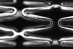
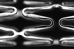
“Because of the critical nature of these devices,” says Tarin, “the US Food and Drug Administration (Rockville, MD, USA; www.fda.gov) mandates 100% inspection. This procedure, currently being performed using stereomicroscopes, is subjective and subject to operator fatigue.” Such manual inspection is made more difficult because each stent is fragile, flexible, and highly reflective. Due to the high magnification involved, the operator is only presented with a limited depth of field so that only approximately one third of the image will be in focus at any particular time (see Fig. 1). To properly inspect each one, 100% surface inspection of both the inside and outside diameter must be made. “Normally,” says Tarin, “this process requires between 140 and 160 different images to be analyzed.”
Tasked with automating this inspection process, Tarin and his colleagues considered using either linescan or area-array cameras. “While the use of area-array cameras would have resulted in easier stent part fixturing,” says Tarin, “more than 170 partially focused 2-D images would need to be captured, a process that could have taken greater than 10 s.” Using a linescan camera, however, results in a single-image acquisition time of less than 1 s at the expense of a more complex part fixturing.
In the system designed by MoviMED, each individual stent is mounted on a custom glass mandrel (see Fig. 2). This is used to keep the stent in focus as it is imaged by a linescan camera and also acts as a backlight for the imaging system. “Since the field of view (FOV) needed to be a maximum of 35 mm and the smallest feature to be resolved was 5 µm,” says Tarin, “the minimum camera resolution required was 35 mm/5 µm, or 7000 pixels. For this reason, MoviMED chose an 8k × 1 Camera Link linescan camera from DALSA (Waterloo, ON, Canada; www.dalsa.com) to capture images of the stent as it was rotated on the mandrel. “With an FOV of 35 mm, this provided a minimum feature measurement of 35 mm/8192 or 4.3 µm/pixel.
“Because stent surfaces are highly reflective, specular surfaces, composed of electro-polished stainless steel, and each stent is rarely straight to within ±50 µm,” says Tarin, “illumination and choice of the correct lens played a critical role in the system design. Because of the specular nature of the stent surface, it must be illuminated by a highly diffused and multidirectional light.” To do this, a custom-developed illumination source was used. This enabled the system to differentiate specular, diffuse, or absorptive features on the surface of the stent.
Similarly, because the size of the image sensor of the Camera Link camera was 57.34 mm, a large-format lens was required. With a field of view of 35 mm, the primary magnification required for this lens was 57.34/35 or 1.68. Because each stent can move within ±50 µm within the FOV of the camera, there is an associated magnification change when conventional lenses are used. For this reason, Tarin and his colleagues chose a telecentric lens from Edmund Optics (Barrington, NJ, USA; www.edmundoptics.com) to substantially reduce such magnification effects.
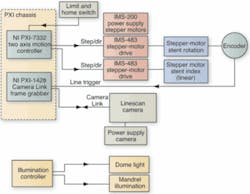
To image each stent in a single pass, the linescan camera is interfaced to a PXI-1428 Camera Link frame grabber from National Instruments (NI; Austin, TX, USA; www.ni.com). To index the stent and rotate it across the FOV of the imaging system, two stepper motors are used. These are in turn interfaced to stepper motor drives from Intelligent Motion Systems (Marlborough, CT, USA; www.imshome.com) and a PXI-7332 two-axis motion controller, also from NI (see Fig. 3). To synchronize the linescan camera to the stent rotation, a rotary encoder mounted on the rotary axis provides a trigger for the frame grabber and, in turn, to the camera.
As the system captures images, they are buffered by the frame grabber and transferred to the host PXI CPU where they are reformatted as single images using NI LabVIEW software. Complete images of single stents are then displayed to the operator on a high-resolution LCD display. “In this way,” says Tarin, “the operator is relieved of using microscope-based methods to view the structure of the stents.”


