Robot workcell corrects dashboard defects
3-D cameras and off-the-shelf software guide robotic twisting of tubes into proper shape.
By Winn Hardin, Contributing Editor
Recently, a European supplier of automotive-dashboard supports approached Automation & Assembly Technologies (A&AT), which builds tooling for the European automotive industry, with a question about how to rework these products. The dashboard support is a steel assembly composed of a long tube with approximately 20 welded subcomponents to connect dashboards to automotive frames.
Occasionally, the heat of the welding process can warp the metal support tube, resulting in misalignment between the holes of the dashboard support assembly and the frame or the dashboard. Parts with distortions that change the geometric relationship between the various boreholes on the dashboard assembly are defective and can cause delays during final automobile assembly if not caught before shipping to the final assembly plant.
The inspections cannot be performed until all parts are welded to the support stanchion, which means parts will be wasted along with metal components should the support be scrapped. The cost of the part dictates that a robotic workcell capable of ‘truing’ the stanchion back into form be cost-effective. A&AT turned to 3-D vision specialist SOLVing3D to adapt two of its PrOMPT.stereo dual-camera photogrammetric systems to measure the 3-D location of key features on the assembly to within 0.1 mm and provide 3-D hole-location data to a hexapod robot so that it can twist and bend the support stanchion back into its correct shape.
Given the part geometry of the support structure, warpage from welding typically resulted in a gradual twist to the support tube or to a bend in the tube. A&AT decided to build a robot workcell that would be powerful and flexible enough to twist and bend the dashboard support to return it to the required geometric specification.
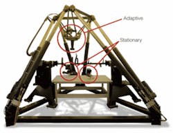
When it comes to increasing power in robotics, workcell designers typically follow this evolutionary path: electrical servos, pneumatic, and finally, hydraulic. A&AT chose a hydraulic hexapod because of its payload power (up to 20 kN). Hexapods have been widely used as mechanical platforms for flight simulators and amusement rides because of their ability to quickly move significant payloads in excess of several hundred kilograms. A&AT needed that power to bend and twist the metal dashboard support assembly back into true position (see Fig. 1).
To return the support structure to its original shape, the robot controller must first know the current shape of the structure and the target shape, or ‘true’ shape, of the structure. When the 3-D coordinates of the existing piece are known, the robot controller can create a program path for twisting and bending the support structure back into true form.
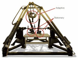
To check and correct the shape of a dashboard support assembly, the operator connects each end of the dashboard support to a separate hydraulic fixture with custom end-of-tooling built specifically for the dashboard support. A custom PLC resides inside the hexapod frame and bookends a workspace table that can be used to temporarily support the dashboard assembly during turnover. The tooling is designed to allow for warpage in the dashboard support. By twisting one or both of the PLC tools, the hexapod controller can correct skew distortion in the dashboard support or rotate the entire assembly so that a bend can be corrected (see Fig. 2).
To correct a bend, a second, inverted hexapod frame is suspended upside down and inside the external hexapod. This secondary platform has both a PrOMT.stereo camera assembly to aid with 3-D measurements and a hammer-like metal bar. The hexapod controller can adjust both the internal and external hydraulic struts to place the metal hammer at the precise location of a bend in the support structure and apply pressure to correct the bend. But first, the full 3-D shape of the dashboard support must be determined.
Photogrammetric Measurements
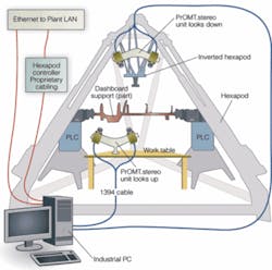
The workcell is located in a dedicated room with extensive fluorescent fixtures to provide full illumination of the part from multiple sources. The workcell uses two PrOMT.stereo sensor units, each with a pair of cameras. One mobile sensor is mounted on the inverted hexapod above the dashboard support, facing down, while the other is fixed to the worktable below the dashboard support.
“We have selected the PrOMT.stereo system because it combines photogrammetric precision with capabilities of a machine-vision system. We can measure many holes simultaneously, which is very useful for our application and helps to save money,” explains Lothar Richter, CEO of A&AT.
The PrOMT.stereo cameras are calibrated to provide precise measurements of the 3-D coordinates (see Fig. 3). The transformation parameters between the coordinate systems of the hexapod and the stereo cameras are computed using photogrammetric techniques (bundle adjustment).

Allied Vision Technologies Marlin F131B sensors in the camera are equipped with Schneider Kreuznach lenses. They are connected via a FireWire 1394a PCI card to the industrial PC, which is equipped with Intel Pentium 4 at 2.8 GHz with 1 Gbyte Ram running under Microsoft Windows XP.
Within PC memory, SOLVing3D triAngle software processes the images. Written in C++, triAngle boosts the MVTec Halcon image-processing library with the addition of mathematic functions especially for the precise computation of the 3-D coordinates. A graphical user interface was developed with Trolltech QT GUI library for the C++ environment.
During the calibration step, nearby scale bars are imaged, and spatial errors caused by optics, thermal variations, and sensor configuration are filtered out based on the known positions of the sensors in the camera and the calibration scale. After calibration, the first dashboard support is loaded into the PLC fixture, and the operator triggers the vision system.
Under constant fluorescent illumination, the two PrOMT.stereo cameras take four images-two pairs of images with each pair sharing a similar field of view, which shows the relative position of each sensor head and the position of a pair of boreholes assigned to each sensor. The triAngle software initiates the Halcon image-processing library, which performs subpixel edge extraction based on a Canny edge finder.
From this calculation, complex features such as drill holes are extracted. The centers of the holes are computed with Halcon’s ellipse fit algorithm. The center points in both images are used to compute the 3-D position based on the geometric relationships between key edges and the known coordinates of the two cameras in the PrOMT.stereo system.That system is designed to work under difficult lighting and reflectance conditions. In many situations, the left and right cameras get the light under completely different angles, and, if the surface of the part under inspection is reflective, the contrast changes significantly. SOLVing3D director Bernd-Michael Wolf says, “Our team works on the enlargement of the existing operators for the detection of drill holes and other features. The challenge is to enhance robustness, speed, and accuracy at the same.”

null