GigE cameras detect fluorescent-tube defects
Six networked GigE cameras detect defects at 70 glass tubes per minute.
By Andrew Wilson, Editor
Since their invention in 1926, fluorescent lamps have been deployed worldwide as cost-saving, energy-efficient replacements for incandescent lamps. Unlike incandescent lamps, however, fluorescent lamps are gas-discharge devices that require a ballast to regulate power flowing through the lamp. In the most common types of tubes, this ballast is located in the glass tube itself, allowing them to be plug-compatible with their incandescent counterparts. Today, most of these fluorescent lamps are 4- or 8-ft fluorescent light bulbs and are usually seen in office buildings and schools.
“However,” says Kurt Haas, senior software engineer with Automation Software & Engineering (AS&E), “before these lamps can be distributed to wholesale and consumer outlets, they must be checked for any possible defects.” To maximize production efficiency, the quality of the glass tubing must be examined before lamp assembly. “By performing quality control early in the inspection process,” says Haas, “manufacturers can maximize the efficiency of the glass-making process while increasing the quality of their products.”
To identify defects, many lighting manufacturers have deployed machine-vision systems. “In some cases,” says Haas, “these are becoming obsolete and must be replaced with simpler, lower-cost systems that use digital cameras. Such was the case when AS&E was asked by a Fortune 100 manufacturer to replace an existing system to both improve the inspection process and make it easier to maintain.
Founded in 1990, AS&E designs and implements process-monitoring, control, and machine-vision systems based on Windows, Unix, and Open VMS. With more than 15 years of experience in developing machine-vision, automation, monitoring, HMI, communications, and web-based applications, the company responded with a system that leverages digital-camera technology, PC-based process control, and networking to analyze the size and shape of unfinished glass tubes to ensure their integrity.
“The manufacture of fluorescent lighting is a multistep process that starts with the creation of a precisely formed glass tube,” says Haas. “When caught early, a less-than-perfect tube can be melted down and reused in the manufacturing process. But if a defective tube progresses too far in the process, it becomes expensive to salvage and handle the electrodes, phosphorus, mercury, and other hazardous substances.”
Through the glass
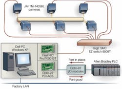
As glass tubes are formed, they are crimped at each end by an end-former to ensure a proper fit for the ballast. After each 4-ft section of tube is crimped, it migrates along a production line where it can be inspected. “Two of the most important features that must be inspected at this stage of the manufacturing process are correct centering of the crimped collar at the end of each tube and whether any bowing has occurred.” says Haas. To do this, six TM-1405GE GigE cameras from JAI are networked through an EZ 8508T GigE switch from SMC Networks. This, in turn, is interfaced to the host PC using an Intel network interface card (see Fig. 1 on p. 26).
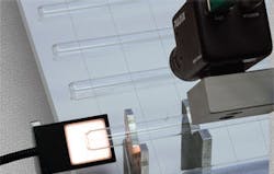
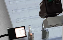
As the glass tubes move along the production line at the rate of 70 tubes per minute, they have to be cut to length, heated, and squeezed at each end to form a slightly smaller concentric opening and are sent past the inspection system by a walking beam that positions each backlit tube under the six-camera apparatus. After triggering a proximity sensor, two cameras, placed perpendicular to one another over the middle of the tube, send images to the host PC to detect any bowing. The remaining four cameras-two at each end-provide images of the formed openings, which are analyzed for size, shape, and concentricity.
Edge detection
“Backlighting plays an essential part in determining whether each part is correctly formed,” says Haas. “At each end of the walking beam two red, square LED lights from Siemens NER backlight the part. Another two NER LED lights illuminate the center section of the fluorescent tube.
“Because the inspection process must determine the edge of the part, it is imperative that these lights are positioned correctly from the part,” explains Haas. “Because glass transmits light, the further away the lights are placed, the more internal reflection there will be within the tube and edge detection will be easier, but the size of the backlight required becomes unworkable. Similarly, if the LED lights are placed too close to the part, then the edge of the tube is more difficult to discern and may, in worse case, disappear.”
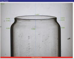
To measure each part for collar centering, two cameras are positioned perpendicularly at each end of the tube. Using the company’s VisTrax C++ image-processing libraries running on the PC, the centerline of the tube is first determined by performing an edge detection on each side of the tube. The centerline of the collar is computed by determining the outer edges of the collar (see Fig. 2). This offset in the x direction is approximately 0.008 in. Similarly, the second camera computes the offset in the y direction. Using both the offset in x and y, the Pythagorean theorem is used to calculate the centricity offset of the collar from the tube.
Edge-detection features are used to compute the amount of tube bowing that may have occurred during manufacture. “Because one cannot assume that the tube will bow downward as it moves along the walking beam,” says Haas, “two cameras also mounted perpendicularly are used to compute the degree of bowing in both the x and y directions.” Using an algorithm similar to that used to compute collar offset, the result is determined and displayed on the system’s graphical user interface (GUI). “The entire inspection process, including capturing images from all six cameras and analyzing the images with VisTrax, takes place in 820 ms.”
Pass or fail
After each part is inspected, a pass/fail decision is determined by the VisTrax software. Should any part fail the inspection process, a ramp actuator is triggered by the PC through optoisolated digital I/O lines to the system’s programmable logic controller. “By moving the ramp from under the walking beam, defective parts fall through the production line onto a second ramp and are transported to a crushing mechanism,” says Haas. “This reduces the glass to cullet that is then recycled to the glass furnace and reformed into more fluorescent tubes.”
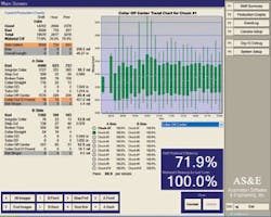
While the software used to perform the image-processing functions was written as a library of C++-based functions, the GUI was developed in C#. “In developing the GUI,” says Haas, “we required the operator to quickly visualize the state of the inspection process and any trends in the manufacturing process (see Fig. 3). By monitoring the production process over numerous shifts, the system can display several trends. These include the number of good and bad parts produced and whether the collar is correctly formed. When plotting these trend charts, the operator can, at a glance, check the system status and discover any faults in the manufacturing process.
“By plotting the collar off-center trend for each of the individual chucks that are used to crimp the end of each tube, for example,” says Haas, “the operator can visualize whether any of the individual chucks need adjusting. These data can also be used by the company’s database-management system for failure prediction and predictive maintenance tasks.”
For AS&E, use of the GigE cameras has provided numerous benefits. The application was quickly developed by taking one of the JAI-provided sample applications, removing a few of the unneeded pieces, and adapting the VisTrax libraries to communicate with the GigE software. Meanwhile, the ability to use affordable Cat5E cabling instead of six-pair, twisted-shielded cables, reduced cabling costs by nearly 75% for the 50-ft cabling run between the cameras and the PC.
Further cost reductions resulted from the use of the switch/NIC combination, which eliminated the need for frame grabbers. The result is a solution that can be adapted to other factory-inspection applications. Already, AS&E is developing a new custom inspection system with GigE cameras for use in a steel-mill environment.
null
