Fiberoptic cables extend frame-grabber use
FRAME GRABBERS
By Andrew Wilson,Editor
Frame-grabber vendors are turning to fiberoptic connectors and cables for Camera Link interfacing over long distances in harsh environments.Last year, a consortium of companies, led by Pulnix America Inc. (Sunnyvale, CA), developed an interface standard called Camera Link to alleviate camera-to-frame-grabber design problems. Already adopted by numerous frame-grabber and camera vendors, this interface is poised to become the de facto standard for digital camera interfaces (see Vision Systems Design, Nov. 2001, p. 34). However, according to Paul Stanton, president of Alacron Inc. (Nashua, NH), there are still too many wires required, cable lengths are too short, and no standard serial optical interface exists. Such a proposed interface standard would be especially useful for harsh environments, where electromagnetic interference (EMI) presents major difficulties when coupling cameras to frame grabbers over long distances.
Initially driven by telecommunications and computer-networking companies that needed to transmit large amounts of data over long distances, fiberoptic connections offer greater bandwidth than do coaxial cables or twisted-pair wires. Moreover, fiberoptic interfaces do not radiate energy, are not susceptible to EMI, and eliminate grounding problems associated with wire-based connections. "In clean environments," says Rene Voorwinden, technical manager at Arvoo Trading (Woerden, The Netherlands), "RS-644/LVDS transmission is possible up to 30 m. However, if longer distances are required, then fiberoptic interfaces must be used," he says.
PROPRIETARY INTERFACESRecognizing the need for point-to-point fiberoptic connections, many camera vendors have developed proprietary interfaces. When these interfaces are used, camera-to-frame-grabber connections can be greatly extended, often over a number of kilometers. The Cooke Corp. (Auburn Hills, MI), for example, offers such a camera/frame-grabber connection for its SensiCam digital imaging system. As a frame-grabber/PCI interface, the system features a cooled CCD camera that offers a number of resolutions, including VGA, SVGA, and 1340 x 1040-pixel resolution with a dynamic range of 12 bits. As an option, developers can implement a fiberoptic link that allows the camera to be placed as far as 1000 m from the host PC."The fiberoptic interface is primarily used as a means of data transmission," says Murad Karmali, Cooke sales manager. "It can only work with Cooke's PCI card, as the protocol of the signal is proprietary," he says. The fiberoptic cable interfaces to two SensiCam subscriber connectors at the back of the camera head. Using a plug and socket with a push-pull latch, these connectors have been used with FDDI, Fibre Channel, and B/ISDN-based systems. In operation, digital image data are transmitted from the camera to the PCI card, and control and timing signals received from the PCI card are delivered to the camera.
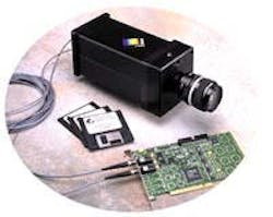
PixelVision Inc. (Tigard, OR) uses a proprietary fiberoptic interface in its range of BioXight camera/frame-grabber combinations (see Fig. 1).
Used as a 14-bit, 80-Mbyte/s, modular camera for physical- and life-science applications, the BioXight product line features resolutions from 80 x 80 to 2048 x 2048 pixels and sensitivity better than 10-9 foot-candles. When configured with CCD sensors in support of high-speed operations, some BioXight cameras can maintain data rates of up to 40-MHz sustained pixel bandwidth (10 Mpixel/s x four outputs). Says Preston Barrett, senior account manager at PixelVision, "All of our cameras use a fiberoptic interface, but since the interface uses a proprietary digital stream, neither PixelVision's cameras nor PCI boards can interface with other cameras."
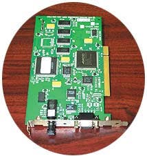
SEARCHING FOR STANDARDSWhereas many camera vendors have implemented proprietary fiberoptic camera-to-frame-grabber interfaces, other OEMs are looking to provide more open solutions. One approach is to use standard off-the-shelf fiberoptic transceiver chip sets such as the Hotlink devices from Cypress Semiconductor (San Jose, CA), the Gigastar parts from Inova Semiconductors (Phoenix, AZ), or the Gigabit transceivers from Agilent Technologies (Santa Clara, CA).Originally designed as a PC interface for the company's line of CCD cameras, the PCI Hotlink board from Wintriss Engineering (San Diego, CA) lets developers load nine bits of parallel data into the transmitter and retrieve the nine bits at the receiver (see Fig. 2). "This makes the Hotlink serial link appear like a parallel interface, but without limited transmission distance and bulky cabling," says company president Vic Wintriss. Using the Cypress Semiconductor chip set to generate the ANSI X3.230 Fibre Channel interface, the board currently supports the company's Opsis 5150 linescan and Opsis 1300 progressive-scan cameras. Both cameras support the Hotlink board running at 330 Mbits/s.
Other camera vendors are also supporting this standard. For a 3-D inspection task, the Ranger camera from IVP (Bloomington, MN) can image up to 10,000 profiles/s from a camera unit. With a built-in StrongArm processor and a C-based application programming interface, designers can implement custom embedded algorithms in the camera unit. When interfaced to the Wintriss PCI Hotlink board, the camera can transmit image data as fast as 330 Mbits/s to the host PC.
Rather than implement the Hotlink chipset directly on the PC board, Nallatech (Orlando, FL) has taken a modular approach by implementing the Hotlink standard as a module for its series of DSP and image-processing-module PCI-based PCI boards. Dubbed the BallyTAXI, the module uses the Cypress CY7C9689 Hotlink, TAXI-compatible transceiver chipset, which allows the transfer of data over serial links at speeds to 200 Mbits/s.
RS-422 PLATFORMSWhile many camera manufacturers are now endorsing Camera Link as the next digital camera standard, many existing digital cameras use the standard RS-422 interface. However, the requirement to couple both RS-422- and Camera Link-based cameras with fiberoptic interfaces still remains a design challenge to many systems integrators."There was no Camera Link interface available at the time of the Alcator C-Mod project at Los Alamos National Laboratory (LANL; Los Alamos, NM)," says Jerry Gaffke, hardware design engineer at Engineering Design Team (EDT; Beaverton, OR). Using a tokamak to confine plasma in a torus, scientists needed to image the surface temperatures in the lower region of the reactor. Using an Amber Radiance 1 camera from Raytheon Corp. (Lexington, MA) coupled to the torus via a re-entrant, 5-m-long ZnSe-based periscope, the high magnetic field surrounding the experiment mandated the removal of the host CPU from the camera module.
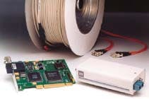
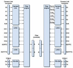
To accomplish this, LANL engineers called on EDT to interface the company's PCI-bus remote camera-interface module (PCI RCI) to the Raytheon camera. The PCI RCI module, a self-contained unit, connects a 1.25-Gbit/s fiberoptic cable to a digital camera with a 68-pin connector using RS-422 signal levels (see Fig. 3 on p. 39). The fiberoptic interface of the PCI RCI module interfaces to EDT's PCI-based fiberoptic interface (FOI) board. In operation, camera data are passed through the PCI FOI board to main memory on the host computer as fast as the camera presents the data. Each PCI RCI module can support a camera with pixel rates to 30 MHz with 8, 10, 12, 14, or 16 bits per pixel.
Although EDT also is currently shipping a half-length PCI board with two Camera Link connectors that support a two Base-, one Medium-, or one Full-configuration Camera Link camera, the PCI RCI system currently supports only standard low-voltage differential signaling (LVDS) or RS-422 camera interfaces. But, according to Gaffke, EDT is planning to introduce support for Camera Link on the PCI RCI soon.
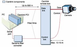
Cat-Science (Budapest, Hungary) also offers a stand-alone unit to interface RS-644 parallel digital output, RS-232/432 serial line-controlled cameras with PCs over a fiberoptic interface. Dubbed Cam Link, the system provides separate data and control fiberoptic-link connections between the host PC and camera (see Fig. 4). The control link provides full-duplex RS-232 or RS-422 serial parameters. Camera parameters can be set and read through this link depending on the camera's capabilities. The data link technology uses S-Link technology, originally developed at Cern (Geneva, Switzerland) and now marketed by Cerntech (Budapest, Hungary). As a unidirectional interface, data are transferred from
ENTER CAMERA LINKWhereas few frame-grabber and camera vendors have endorsed the Hotlink standard, many have opted to use the Camera Link standard. As reported in last month's Product Focus, more than a dozen frame-grabber vendors and many more camera manufacturers have endorsed the standard by introducing Camera Link-compatible products. Although structured as a serial point-to point connection, Camera Link does provide data rates to 680 Mbytes/s across 26-pin Micro Delta Ribbon (MDR) connectors.As yet, however, a fiberoptic implementation of the Camera Link standard has not been implemented in a frame grabber or camera offering. Although Dalsa Imaging (Waterloo, Ont., Canada), for example, has no existing fiberoptic interfaces on its cameras at present, third-parties, such as PLD Applications (Aix-en-Provence, France), have developed a fiberoptic interface to the Dalsa Piranha camera (see "Linescan cameras monitor rail integrity in real time" on p. 43) the camera to the host. Some return lines are also provided that enable control of the CamLink remote system from the host computer.
Because many frame-grabber and camera vendors are endorsing Camera Link, some companies are offering external fiberoptic adapters. In operation, these adapters allow a Camera Link-compatible camera or frame grabber to communicate over fiberoptic links. At the recent Vision Show East, Jack Okabayashi of Inova Semiconductors (Phoenix, AZ) announced that his company has developed such an interface for a government application. Although Inova would not release details, the company is preparing a similar design for a surveillance application. According to Okabayashi, design details on this interface will be available in a few months.
While systems integrators await the design of frame grabbers and cameras with built-in fiberoptic interfaces, companies such as Arvoo Trading, PhotonAge (Fremont, CA), and Stac (Fujimi Sayama-shi Saitama, Japan) offer stand-alone interface boxes. In operation, these interfaces convert the output from a Camera Link-compatible camera to a fiberoptic transceiver, which transmits data over long distances, often as much as several kilometers, to another transceiver that converts the signals back into Camera Link format. These signals can then be interfaced to a standard Camera Link-compatible frame grabber.
According to Arvoo's Rene Voorwinden, the company's OpticLink Camera Link-to-fiber interface is available for RS-644/RS-422 (LVDS), Camera Link Base/Medium/Full configurations, and IEEE-1394 (FireWire) based cameras (see Fig. 5). Four models have been designed to connect Camera Link Base-configuration 16-bit, Base-configuration 24-bit, Medium-configuration 48-bit, and Full-configuration 64-bit cameras. "The difference between Base-configuration 16-bit and Base-configuration 24-bit is the number of fiberoptic cables needed," explains Voorwinden. "While the Base-16-bit version requires one duplex fiberoptic cable, the Base-24-bit version uses two duplex fiberoptic cables. Since many Camera Link cameras deliver only 8, 10, or 12 bits, the Base-16 model is a less expensive option for these cameras," he adds.
PhotonAge offers a similar fiberoptic-Camera Link interface. The company's CLextender is a direct plug replacement for Camera Link Base-configuration cable applications. It consists of a cable of multimode fibers terminated at each end with an interface box to which a Camera Link cable extends. These interface boxes are used to convert low-voltage differential signals to optical signals and then back to LVDS signals at each end of the cable. According to Russ Theilig, vice president of sales and marketing at PhotonAge, the CLextender cable extends the use of Camera Link cameras at maximum data rates of 40 MHz over distances to 500 meters.
Nobuhiko Ozaki and his colleagues at Stac in Japan also have developed a Camera Link interface called the CLE-10KTX/RX modular interface box. At present, data regarding the product are only available in Japanese, although the company is currently writing English documentation. The product is said to convert image data from Camera Link-compatible cameras and transmit that data via fiberoptic cable to another transceiver. According to the company's Web site, the product supports a maximum 10-km transmission distance using single-mode fiber.
GETTING ON-BOARDDespite the recent spate of Camera Link-to-fiberoptic support products, neither camera nor frame-grabber vendors are rushing to support a fiberoptic-like Camera Link standard. "Although we are currently developing Camera Link-interface frame grabbers," says Stephane Francois, executive vice president at Leutrek Vision (Burlington, MA), "we wonder about the viability of the Camera Link standard if fiberoptics becomes the preferred connection support. We think standardized communication protocols are also needed."John Vieth, Dalsa director of product management and marketing, is also concerned about the number of fiberoptic-communication protocols now available. "By itself, Camera Link cannot serve as a panacea for all interface challenges across all applications," he says. "But the machine-vision industry would not be well served by replacing the long needed Camera Link standard with a myriad of proprietary fiberoptic connections between cameras and computers. The best choice is to offer fiberoptic interconnect products that work with standard Camera Link interfaces at the camera and at the computer. This provides system integrators with the means to implement fiberoptic connections, where warranted, without restricting their choice of camera or frame grabber."
Taking up this challenge, Datacube (Danvers, MA) already offers a fiberoptic camera interface board, the MaxVideo 2000. It uses on-board transceivers from Agilent Technologies. In operation, the board can support as many as four channels of video data at speeds to 100 Mbytes/s. "To interface this fiber to Camera Link-based cameras," says Tom Hospod, Datacube vice president of marketing and business development, "the company offers an LVDS/Camera Link system built around a stand-alone VME board."
In operation each sensor interface can handle as many as four 25-MHz LVDS taps from digital cameras. Consequently, four sensor interfaces can support up to 16 cameras on one MaxVideo 2000 board. "At present," says Hospod, "the Camera Link interface board is priced at $1500. However, the company has plans to reduce the size of the sensor interface to a 2 x 2-in. module that could possibly be embedded in digital cameras. Currently supported cameras include Basler's 113, A201, and L160; Atmel's Camelia 8M; and Kodak's MegaPlus 1.4i.
See p. 44 and the Vision Systems Design Buyers Guide for more information on suppliers of frame grabbers.
____________________________________
Linescan cameras monitor rail integrity in real timeFrance has been in the vanguard of high-speed passenger rail travel and now has a modernized rail network capable of accommodating trains running in excess of 300 km/h (186 mph). The Train à Grande Vitesse (TGV, or high-speed train) initially deployed in France runs on a rail network that stretches into Belgium, Germany, Switzerland, and Italy. Under control of the French government—Societe Nationale des Chemins de Fer Français (SNCF)—the National Railway Company of France must provide rail transport and manage the rail infrastructure on behalf of Réseau Ferré de France (RFF), the rail infrastructure's owner.
To manage and maintain the rail infrastructure, SNCF contracted Cybernetix (Marseille, France) to build a system capable of inspecting rail track in real time. "Because of the speed of the trains and the miles of track deployed," says Nicolas Long, a vision research engineer with Cybernetix, "it is impossible to manually inspect the track. This would require interrupting high-speed train service and, at the same time, would prove dangerous to track inspectors," he says. Instead, the rail tracks are inspected at speeds of up to 300 km/h using a vision-inspection system on-board the TGV.
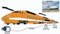
Long and his colleagues developed a PC-based system using off-the-shelf linescan cameras, frame grabbers, and PC motherboards. Because it was necessary to image the track at 300 km/h, two Dalsa Piranha 80-Mbyte/s, 512 x 1 x 8-bit linescan boards are housed in the TGV to image the two rail tracks. "Because the TGV is powered by electricity from overhead wires," says Long, "it was necessary to build an interference-proof fiberoptic interface to transmit data 250 ft from the camera to a PC-based frame grabber at the center of the train."
For this task, Cybernetix contacted PLD Applications (Aix-en-Provence, France). "Fortunately," says Arnauld Schleich, vice president of sales and marketing at PLDApplications, "Dalsa cameras such as the Piranha allow custom boards to be added as modules at the rear of the camera." To interface the fiberoptic output of the Dalsa camera to the frame grabber, PLDApplications supplied a fiberoptic interface to the company's smart Xsys frame grabber. The 64-bit, 66-MHz PCI-based frame grabber board can transfer image data at up to 528 Mbytes/s in bus-master mode to a host 64-bit, 66-MHz Intel Xeon PCI-based motherboard.
To transfer two 40-Mbyte/s linescan images to the frame grabber, two Agilent-based fiber-optic interfaces are mounted on the Xsys frame grabber using PMC connector ports. As images are captured by the host PC, the region of interest (ROI) of the captured images is located by real-time ROI algorithms embedded in a gate array on the frame-grabber board. After the ROIs have been located, ROI data are passed to the host PC, where custom surface-inspection algorithms are used to determine the integrity of the track. At the same time, real-time image data from both cameras are passed through fiberoptic-connected mezzanine boards to a second PC. Housing a similarly configured PC/fiberoptic-based frame-grabber combination, real-time image data are then compressed in JPEG format and stored to three 180-Gbyte Ultra-SCSI drives.
____________________________________
Company InformationDue to space limitations, this Product Focus does not include all the manufacturers of the described product category. For information on other suppliers of frame grabbers, see the 2001 Vision Systems Design Buyers Guide (Vision Systems Design, Feb. 2001, p. 98).
Agilent Technologies
Santa Clara, CA 95054
Web: www.agilent.com
Alacron
Nashua, NH 03060
Web: www.alacron.com
Arvoo Trading
3440 AK Woerden
The Netherlands
Web: www.arvoo.com
Cat-Science Bt.
Budapest, Hungary
Web: www.catscience.kfkipark.hu
Cerntech
Budapest, Hungary
Web: www.cerntech.kfkipark.hu
(The) Cooke Corp.
Auburn Hills, MI 48326
Web: www.cookecorp.com
Cybernetix America
Cambridge, MA 02142
Web: www.cybernetix.fr
Cypress Semiconductor
San Jose, CA 95134
Web: www.cypress.com
Dalsa
Waterloo, Ont., Canada N2V 2E9
Web: www.dalsa.com
Datacube
Danvers, MA 01923
Web: www.datacube.com
Engineering Design Team
Beaverton, OR 97006
Web: www.edt.com
Euresys
El Cajon, CA 92019
Web: www.euresys.com
Inova Semiconductors
Phoenix, AZ 85016
Web: www.inova-semiconductors.com
IVP
Bloomington, MN 55438
Web: www.ivpvision.com
Leutrek Vision
Burlington, MA 01803
Web: www.leutrek.com
Nallatech
Orlando FL 32826
Web: www.nallatech.com
PhotonAge
Fremont, CA 94539
Web: www.photonage.com
PixelVision
Tigard, OR 97223-4310
Web: www.pvinc.com
PLDApplications
Aix-en-Provence Cedex 3
France
Web: www.plda.com
Pulnix America
Sunnyvale, CA 94089
Web: www.pulnix.com
Stac
Fujimi Sayama-shi Saitama
350-13, Japan
Web: www.stac.co.jp
Wintriss Engineering
San Diego, CA 92121
Web: www.weco.com
