Machine vision speeds robot productivity
By Andrew Wilson, Editor
Two technologies—machine vision and robotic automation—are rapidly coming together to propel manufacturing automation to higher reliability levels at faster speeds. Reflecting the latest product improvements, systems that are integrating these technologies differ dramatically from those deployed during the early times of manufacturing automation. Back then, most robot vendors offered proprietary, closed-architecture systems that combined vision and robot guidance in a single, but expensive, system. Today, however, with the advent of low-cost smart cameras, PC-based frame grabbers, and pattern-matching software, many suppliers and systems integrators are merging the best features of available machine-vision and robotic-control systems. And, whereas complete systems are relatively expensive, ranging from $100,000 to $1 million, plant managers are receiving relatively fast payback periods of between one and two years, making such an investment cost-efficient.
"Today's systems integrators are demanding systems that are easy to tailor," says Ed Roney, manager of vision product and application development at Fanuc Robotics (Rochester Hills, MI). "In particular, they need graphical programming tools that allow vision tools such as pattern matching to be rapidly integrated with motion control systems using interfaces such as RS-232 and Ethernet," he adds.
Jack Justice, market segment manager with Motoman (West Carrollton, OH) agrees. "Years ago, I would only recommend the use of vision as a last choice alternative," he says, "but over the past few years, companies such as Cognex Corp. (Natick, MA) and DVT Corp. (Norcross, GA) have introduced low-cost vision systems that are both easy to integrate and maintain on the shop floor."
Ease of programmability, Ethernet conductivity, and low cost are the major advantages being obtained by systems integrators building combined robot and vision systems. To address these needs, vision vendors such as Cognex and DVT are being used in a number of projects that previously required separate frame grabbers, PCs, and imaging software. And although open PC-based systems can offer advantages in some types of applications, it certainly appears that the move towards more fully integrated smart camera systems is heralding a new era in manufacturing automation.
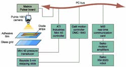
Systems integrationIn automation-system applications that range from medical-device inspection to automotive-parts manufacturing, machine-vision and robotic-vision systems are forging into new territories. "Nearly every other automation system we develop incorporates vision," says Mark Meske, vice president of automation at Ellison Machinery Company (EMC; Pewaukee, WI), "because the combination of vision and robotic systems means less front-end work has to be performed in any given systems design."FIGURE 2. Metro Automation has developed an inspection system for the automated production of laser semiconductor diodes. The vision-assisted placement system takes individual die strips and places 50 of them side by side on an adhesive film. Once mounted, a scribing machine is then used to separate die 50 times faster than was previously possible. Developed around the Seiko Vision Guide PC, the system ties together precision motor stage, machine-vision, force-feedback, and robot automation systems.
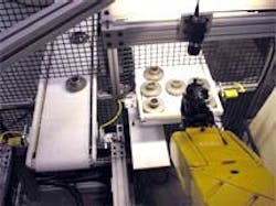
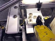
Under contract to a manufacturer of motor gears, EMC has developed a system that uses both vision and robots to pick, machine, and measure gears.
Previously, this operation was performed manually by three operators whose throughput was roughly 30 s per part. To automate the CNC and inspection process, EMC installed a PC-based vision system that controls an LRMate200i robot from Fanuc (see Fig. 1). Costing approximately $200,000, the payback period for the system, including the CNC machine, is between one and two years. Based on the success derived from the first work-cell station, EMC's customer has added a second vision system.
During system operation, unfinished gears are positioned on a conveyor belt controlled by a programmable logic controller (PLC). After a beam sensor detects the presence of a gear, the conveyor belt is stopped, and images of up to three gears are taken by an overhead RS-170-based camera from Pulnix America Inc. (Sunnyvale, CA). These images are then digitized by a visLOC PC-based vision system from Fanuc, and the positional or offset data are sent to the associated robot over the PC's built-in Ethernet interface.
After the gear is picked by a 200i robot fitted with a three-jaw double-gripper, it is turned over and presented to another Pulnix CCD camera. Images of the gear from the second camera are compared to known good threshold values stored in the PCs database. When a gear is accepted as good, it is placed on a three-pin chuck fitted to a CNC machine for a milling operation. After milling, the robot's primary gripper unloads the turned gear while the second gripper loads the next gear.
Although the visLOC system used in EMC's design uses the Cognex 8100 MVS-8100 machine-vision hardware and software package to digitize, process, and display images, the visLOC's user interface builds on the Cognex machine-vision tools supplied with the MVS-8100 board. According to Fanuc's Ed Roney, the visLOC package fits 90% of robot-guidance applications, including EMC's.
As a stand-alone system, however, additional machine-vision and image-processing commands cannot be added to visLOC. "Our systems integrators do not want to deal with development tools. "They would rather develop systems using a visual development language that presents them with a graphical user interface that leads them through the vision deployment process."
Semiconductor inspection Like Fanuc, Seiko Instruments USA (Torrance, CA) also packages a PC-based vision front end with its motion controllers and robots. Dubbed Vision Guide, the system consists of a bundled Pulsar frame-grabber board from Matrox Imaging (Dorval, Quebec, Canada), an MIB robot communications card, and the company's Vision Guide 3.0 software. "Running under Windows NT, the software was primarily developed to provide the machine-vision tools necessary for robot-guidance applications," says John Clark, Sieko vice president of sales and marketing. Unlike Fanuc's visLOC package, however, the system can be tailored to meet the needs of a number of industrial automation applications.One such company that has taken this approach is Metro Automation (Grand Prairie, TX). There, Michael Doke, vice president of engineering, and his colleagues have developed an automated system for producing laser diodes. Developed for a large telecommunications company, the system speeds up the scribing process that separates individual laser diodes from wafer strips. "These strips are generally 0.75 in. long and measure 0.012 in. wide," says Doke. "In the past, the 50 individual diodes located on the strip were separated manually on a die-cutting machine," he adds. This was a tedious, time-consuming process that was prone to error.
To overcome these problems, while increasing throughput, Metro Automation developed a vision-assisted placement system that takes individual die strips and places 50 of them side by side on an adhesive film. Once mounted, the scribing machine can then separate 50 times as many die in one operation. "To achieve the precision required, however," says Doke, "each die strip must be aligned to any other die on the film to within 5 µm."
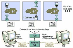
FIGURE 3. To automatically inspect blow-molded automotive gas tanks, the positions of a series of features such as holes or weld pads must be established. However, due to the blow-molding manufacturing process, the gas tanks tend to shrink and warp such that the positions of the location details vary from their original positions on which the robot paths were taught. By using a set of cameras to detect these shifts and report the information to a PLC, the robots can adjust their target positions in the x and y directions and properly place each individual tank at the next assembly process.
Faced with this seemingly dauntless task, Metro Automation developed a robot and vision machine in less than five months using custom-built and off-the-shelf components. Developed around a Seiko Cartesian robot and Vision Guide software, the system ties together precision motor stages and machine-vision and robot automation systems (see Fig. 2). At the heart of the system is a precision x-y stepping slide from Bayside Motion Group (Port Washington, NY), which is operated under control of a DMC1840 motion control board from Galil Motion Control (Rocklin, CA).
Metro Automation contracted Advanced Reproduction Corp. (Andover, MA) to develop a glass-registration grid scribed with 10-µm lines, 100 µm apart. After transparent adhesive film is placed over the glass grid, the system is ready to place diode strips. Under control of robot commands driven from a Visual Basic interface, a Seiko XM-3023 robot with a vacuum-based end effector picks laser-diode strips from a known location. Then, the part is placed under a Pulnix TM-1001 1k x 1k-pixel camera located 3 in. from the adhesive surface.
After images are captured by the camera, they are digitized by a Matrox Pulsar board in the Seiko PC system, then checked using Vision Guide software for picking accuracy, and next placed within 7 µm of a grid line on the glass positioned above the adhesive film. To provide the 5-µm accuracy required, the camera is then automatically focused on the glass slide, and an index stepper is aligned using the laser-cavity fiducial already computed from the initial image-capture operation.
After the stepper motor positions the slide, the custom-built end effector places the component strip on the adhesive surface of the film. "At this stage," says Doke, "the pressure exerted to place the component strip must be carefully measured." To do so, a Mini 40 pressure transducer built into the end effector measures the force exerted by the robot. This measurement is then interfaced to the host PC using an ISA bus-interface card from ATI Industrial Automation (Apex, NC). Under control of the user's PC interface and the Seiko controller, this process is repeated until all 50 component strips are placed on the adhesive surface. The fully populated surface is then moved to a manually operated scribing station where individual diodes are produced. The machine is being shipped to Metro Automation's customer this month.
Blow-molded tanksAlthough systems integrators such as Metro Automation are using more bundled vision systems in their automation projects, other machine-vision tasks are being accomplished with off-the-shelf imaging software. Such an application faced Braintech (North Vancouver, BC, Canada) when approached by ABB Flexible Automation Canada (Burlington, Ontario, Canada) to develop a vision system to automatically inspect blow-molded automotive gas tanks.Because each gas tank possesses a series of features such as holes or weld pads that are used for various types of assembly such as for the plastic welding of clips and pipes onto the tank, it is important that the positions of these features are defined. However, due to the blow-molding manufacturing process, the gas tanks tend to shrink and warp such that the positions of the feature details vary from the original positions upon which the robot paths were taught. By detecting these shifts and reporting the information to a PLC, the robots can adjust their target positions in the x and y directions and arrive exactly at where the feature details are located for each individual tank.
During operation, the vision system provides the gas-tank processing-line supervisory PLC with accurate shift values for each selected feature on the gas tank. The required accuracy in measuring x and y shifts is ±0.25 mm. To accomplish this, Braintech engineers developed a PC-based vision system capable of accepting up to six camera inputs, with each camera viewing a single feature on the tank (see Fig. 3). During the visual inspection process, the gas tank is fixtured in a series of six work cells, each of which feature separate machine-vision and robot systems linked over Ethernet to PCs.
When a gas tank is ready for inspection, a specific identification tag on the tank is located by each vision system. Once this specific feature has been identified, its position is calculated with respect to a "golden" position recorded during a previous training session. Then, x and y shift values are sent to an Allen-Bradley/Rockwell Automation (Milwaukee, WI) PLC using the Distributed Data Exchange format via an RSLINX communications server developed by Rockwell Software. This operation facilitates the link between PC-based applications and the Allen Bradley PLCs. The ABB Flexible Automation robots are then used to properly position the gas tanks for the next stage of the manufacturing process.
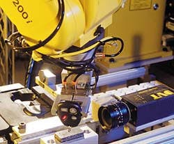
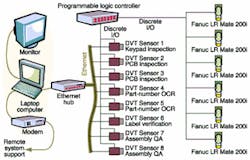
Automotive assemblyWhereas companies such as Braintech are using OEM imaging equipment in their projects, other companies are turning to smart sensors or cameras to solve their system-development tasks. For example, GSMA Systems (Palm Bay, FL) was recently contracted by a major automotive supplier to provide a vision system for checking keyless remote-entry parts. "In the design of the system," says Mark Senti, president of GSMA, "the main requirement was to utilize a common solution for the variety of inspections. We chose a stand-alone, modular vision system that could be easily programmed and connected via Ethernet."GSMA developed a system based around eight DVT Corp. Series 600 Smart Image sensors networked over Ethernet and six Fanuc LRMate 200i six-axis robots (see Fig. 4). "In operation," says Senti, "the system automatically inspects and assembles key-fob transmitters. Each transmitter includes front and back covers, keypad, printed-circuit board (PCB), and key ring." The final product after assembly is a keyless remote set that consists of two key fob transmitters and one receiver tie-wrapped together as a set. These sets are then shipped to car manufacturers.
The robotic production line consists of a number of separate workstations at which an inspection and assembly process is accomplished. Initially, a vibratory feeder is used to feed two separate key-fob case shells to a fixture where a date stamp is applied. After date stamping, keypads are inserted into their housing and inspected by a DVT Series 600 sensor system that verifies the correct graphics on the keypad. "To perform this inspection," says Senti, "the DVT Series 600 systems are taught images of the different keypads used in the product. The smart camera is then programmed to perform pattern-matching on each part type. Part types are communicated to the camera via a line controller and Ethernet."
At the same time, the PCB used in the key-fob shell is inspected at another workstation that checks the identification code of each board. Once verified, these boards are robotically placed inside the transmitter assembly. Using another Series 600 smart sensor, the back shell of the key fob is imaged using optical-character-recognition imaging to verify part type. After inspection and assembly, the transmitter set is conveyed to a verification station to check for complete assembly. The next workstation attaches a key ring to the key fob and inspects key ring quality with another Series 600 sensor.
Keyless receivers are also automatically assembled on an adjacent vision system. Inspections using the Series 600 on this line verify the receiver PCB, cover, and barcode number. The transmitter set and receiver are then robotically loaded into a tie-wrapping cell that joins the components together as a set.
"In the development of the vision system," says Stu Geraghty, GSMA senior systems engineer, "machine-vision software was developed off-line on an Ethernet-connected laptop PC using DVT's FrameWork software." Eight smart cameras were taught an array of parts for part number, part type verification, or part quality inspection before being deployed on the production line. The full assembly-line throughput is one set every 6 to 8 s, costing approximately $1 million, with an estimated payback period of less than 1.2 years.
Medical manufacturingIt's not just systems integrators that are developing integrated automated manufacturing systems using off-the-shelf machine vision and robotic-control systems. Robot vendors themselves often use their in-house systems integrators to supply end-users with integrated vision solutions. For example, according to Carl Traynor, director of marketing at Motoman, the company's advanced systems group is generating more than $40 million annually from the sale of such systems. But rather than field its own proprietary vision system, the company prefers to use off-the-shelf vision systems in these designs.Like GSMA systems, Motoman has used Cognex In-Sight and DVT Series 600 vision sensor systems in such designs. In a recent project, Motoman developed a vision system for a major medical manufacturer that verifies the presence or absence of parts contained in intravenous (IV) drip bags. If the IV bags do not contain the correct number of parts, they are left on the conveyor belt while good parts are automatically removed and packed for shipping.
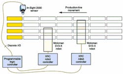
During drip-bag inspection, a Cognex In-Sight 2000 vision sensor is positioned over a conveyor belt (see Fig. 5). As each line of eight drip bags reaches the inspection station, a proximity sensor linked to an Allen Bradley SLC504 PLC stops conveyor movement, and the sensor images a set of IV bags. After the sensor's processor performs a parts-verification function on each image, the pass/fail information is transmitted to the PLC using the I/O interface of the vision sensor. Data from the sensor are then passed to two Motoman XRC robot controllers that control the motion of two Motoman SV3 robots. "This application," says Carl Traynor, "required the use of two robots to increase the packaging throughput of the system."
According to Greg Morgan, Motoman software engineer, the In-Sight 2000 vision system was chosen because of its easy-to-use Excel-like programming tools. "By using this spreadsheet," he says, "pattern-matching tools such as PatFind could be easily programmed to locate specific parts in the images. Then, the system's edge-detection and blob-analysis tools were used to determine whether the correct parts were placed in the IV package."
FIGURE 5. Motoman system verifies the presence or absence of parts contained in intravenous drip bags. If the bags do not contain the correct number of components, they are left on the conveyor belt while good parts are automatically removed and packed for shipment. During operation, the camera is positioned over a conveyor belt containing the bags. As each line of eight bags reaches the inspection station, a proximity sensor triggers the conveyor to stop while the system images the bags. After the sensor performs parts verification on each image, pass/fail information is transmitted to the PLC and two robots are instructed to pack good products for shipping.
Costing approximately $150,000, the installed system took approximately 16 to 18 weeks to develop. "Using off-the-shelf vision," says Morgan, "meant that the machine-vision development of the system was reduced to between 40 and 60 hours."
Company InformationDue to space limitations, this Product Focus does not include all the manufacturers of the designated product category. For information on other suppliers of robots and vision systems, see the 2001 Vision Systems Design Buyers Guide (Vision Systems Design, Feb. 2001, p. 97).Allen Bradley/Rockwell Automation
Milwaukee, WI 53204
Web: www.ab.com
ATI Industrial Automation
Apex, NC 27502
Web: www.ati-ia.com
Bayside Motion Group
Port Washington, NY 11050
Web: www.bmgnet.com
Cognex Corp.
Natick, MA 01760
Web: www.cognex.com
DVT Corp.
Norcross, GA 30093
Web: www.dvtsensors.com
Ellison Machinery Co.
Pewaukee, WI 53072
Web: www.ellisonmachinery.com
FANUC Robotics
Rochester Hills, MI 48309
Web: www.fanucrobotics.com
Galil Motion Control
Rocklin, CA 95765
Web: www.galilmc.com
GSMA Systems
Palm Bay, FL 32905
Web: www.gsma.com
Matrox Imaging
Dorval, QC H9P 2T4, Canada
Web: www.matrox.com/imaging
Metro Automation
Grand Prairie, TX
Tel: (972) 606-2184
Motoman
West Carrollton, OH 45449
Web: www.motoman.com
Pulnix America Inc.
Sunnyvale, CA 94089
Web: www.pulnix.com
Seiko Instruments
Torrance, CA 90505
Web: www.seikorobots.com
