Military researchers focus low-light imaging on Fuel Nozzle Design

Military researchers focus low-light imaging on Fuel Nozzle Design
By Lawrence J. Curran, Contributing Editor
Fuel mixture and pressure inside the jet engines that thrust military missiles to blazing mach speeds must be maintained at optimum levels for efficient engine operation. In fact, the US Air Force is currently testing various fuel-injector designs for a scramjet--a supersonic-combustion ramjet planned to achieve speeds ranging from Mach 4 to 25. Toward that goal, engineers and scientists at Wright-Patterson Air Force Base (WPAFB; Dayton, OH) are using low-light-level imaging to help them design the optimum fuel-intake-nozzle configuration for the scramjet combustor, a daunting task, according to WPAFB engineers.
Jet-engine research is being conducted by the Air Force Research Laboratory(AFRL) Propulsion Group at WPAFB, assisted by researchers from Innovative Scientific Solutions Inc. (ISSI; Dayton, OH). Cam Carter, a research scientist at ISSI, says a large part of the work is aimed at understanding how best to inject fuel into the combustor`s supersonic freestream air flow to achieve rapid mixing of fuel and air while also minimizing pressure loss.
Maintaining adequate pressure is important in achieving the engine`s desired thrust. That`s the area where low-light-level imaging is making an important contribution by capturing images of the fluorescence of pressure-sensitive paints (PSPs) applied to the injectors. The fluorescence imaging is then used to calculate the pressure associated with two different injector designs used in the tests to date. The AFRL experiments also measure heat loads on the combustor wall to assure that the cooling system can control the heat, preventing structural damage to the combustor.
One prospective scheme being considered uses either circular or elliptical injectors that exhaust perpendicularly into a supersonic freestream at Mach 2 speed. Results of the initial tests indicate that an elliptical injector might be the more effective design, but testing continues using variations of both styles to determine how to achieve the optimum mixture and pressure profiles for ideal combustion.
In the work to date, a back-illuminated CCD camera and software from Pixel Vision Inc. (Beaverton, OR) are acquiring images that provide researchers with valuable temperature and pressure data (see Fig. 1). In the AFRL work, the CCD camera was mounted above the supersonic combustion tunnel segment (see Fig. 2). The camera looked down through a quartz window in the test section.
Two pressure paints were used to help measure the pressure distribution about the circular and elliptical injectors. One paint consists of a Pyrene base with a silicone binder. The silicone is a low-molecular-weight conformal coating, which suits pressure paint applications. When excited by laser light, this paint emits in the visible light region between 400 and 500 nm; it generates strong monomer and excimer emissions that are both pressure-sensitive. However, the Pyrene`s fluorescence lifetime is very short (300 ns under vacuum), making it relatively insensitive to its thermal environment.
The second paint consists of platinum octaethylporphyrin (PtOEP) oversprayed onto a white paint layer. The PtOEP paint absorption maximums are at 390 and 540 nm, with emission at 650 nm. This paint demonstrates a strong sensitivity to both oxygen and temperature. Its stronger sensitivity to temperature than the Pyrene paint results from its relatively long phosphorescence lifetime of 150 ms under the same vacuum conditions.
Imaging setups
Two experimental setups collected images of the pressure fields while using the two different pressure paints. Figure 1 shows the experimental arrangement for obtaining PSP images using the Pyrene-based paint. A Model GL3300 pulsed nitrogen laser from Photon Technology International Inc. (Monmouth Junction, NJ) provided the 337-nm excitation source for the probe molecule (Pyrene) in the PSP. This laser was remotely triggered using an HP8112A pulse generator from Hewlett-Packard Co. (Santa Clara, CA). Laser light was transmitted to the injector block over a fiberoptic cable.
This method allows precise illumination of the fuel-injector model. A PixelVision SpectraVideo model SV512V1C back-illuminated CCD camera collected the fluorescence from the PSP. The back-illuminated CCDs that form the core of PixelVision`s cameras are fabricated by Scientific Imaging Technologies Inc. (Beaverton, OR). The camera has a Nikon f/1.8 50-mm lens to obtain the desired image field of view. A PixelVision camera controller was interfaced to a Pentium PC running PixelView data-acquisition software under Windows 95. A model 9314L oscilloscope provided by LeCroy Corp. (Chestnut Ridge, NJ) monitored the laser and camera pulses.
A similar arrangement was used for the PtOEP-based pressure paint, except that a 5-W frequency-doubled continuous-wave Nd:YVO4 laser from Spectra-Physics Lasers (Mountain View, CA) provided the excitation energy. Approximately 750 mW of laser power was delivered through a fiberoptic cable to a Lambertian scattering plate and directed onto the painted surface. The scattering plate minimized the large speckle that occurs because of self-interference in the fiberoptic cable with the spectrally narrow laser.
Because the scattering plate was Lambertian, the amount of light hitting the painted surface was only a small fraction of the 750-mW output of the laser, thereby reducing problems associated with photodegradation of the paint. A 10-ms camera shutter was used in conjunction with the ƒ/1.8 50-mm lens and back-illuminated CCD camera to acquire these images.
PixelVision`s senior scientist Mark Nelson says the camera controller operates off the pulse generator to synchronize the acquisition of an image with activation of the pulsed laser-light source. The combination of PixelView software and the PCI input/output (I/O) interface card are key elements in the camera`s performance, Nelson says. These elements enable the capture of two images simultaneously, and more than one I/O card can be interfaced to a PC. In fact, one such card can drive as many as four cameras."Virtually any computer with a PCI bus will run our PCI board and software in a master slot," he adds.
There is no need for a frame grabber in the PixelView imaging subsystem. The PCI interface card functions as a line grabber or buffer, taking in one line of data at a time. There are two line buffers in the interface card. When one buffer fills, it generates an interrupt to the PCI controller chip, which triggers a DMA transfer of that data to PC memory and makes the second buffer available to take in another line. CCD clocking is controlled by a digital-signal-processor (DSP) chip in the camera control unit; the DSP is an ADSP-2100 series device from Analog Devices Inc. (Norwood, MA).
Data analysis
Data acquisition in the AFRL study consisted of taking 10 background images, 10 wind-off images, 10 vacuum images (where the exhausters of the facility operated without air flow), 20 wind-on images at four different injector pressures, and 10 postrun wind-off images. Because the vacuum images were taken at a known pressure, they represented another reference point for comparison. ©
The data analysis of the PSP images involved several steps. First, the images in the various ensembles were averaged. Then the average background was subtracted from each of the averaged wind-on and wind-off images. Next, the wind-on images were shifted to ensure good overlap with the wind-off images. The resulting wind-on images were then divided into the wind-off images, and these ratioed images were finally converted from intensity to pressure by applying the calibration data obtained in static calibration apparatus.
Image shifting was necessary to ensure optimum alignment of the wind-on and wind-off images. The typical shift was found to be 0.5 pixel along the rows and columns of the array. This process was accomplished by expanding the original 516 ¥ 516-pixel array to 2064 ¥ 2064 pixels using a bilinear interpolation, shifting the image by the appropriate amount, and then compressing the image back to the 516 ¥ 516 size for pressure analysis.
The most significant advantage of the PSP technique over conventional pressure measurements is the ability to simultaneously acquire a large two-dimensional array of pressure data with tremendously improved spatial resolution. The physical dimensions of the displayed region are approximately 79 mm in the freestream direction (the direction of the freestream flow) and 80 mm in the spanwise direction (looking downward at a 90° angle to the freestream direction). Each pixel in the displayed region is 0.187 mm square. Pressure taps machined into the hardware for these experiments are roughly 0.75 mm in diameter. Thus, the pixel dimensions yielded a pressure measurement that was averaged over 0.035 mm2, whereas the pressure taps were averaged over about 0.46 mm2.
The improvement in spatial resolution over conventional taps becomes evident by considering that each PSP image represents nearly 180,000 pressure measurements in a 79 ¥ 80-mm area (see Fig. 3).
Experiments continue
Imaging analysis of the data obtained using the two pressure-sensitive paints enabled the AFRL researchers to compute the effective back pressure observed for the two types of injectors. The data will aid in ongoing efforts to determine the optimum fuel combustor design for a scramjet engine. It indicates that the pressures associated with the elliptical injectors are 20% to 35% greater than the respective results using the circular injectors. This means the jet leaving the elliptical zone encounters a higher-pressure environment than does the circular jet under the same operating conditions.
ACKNOWLEDGMENT
Portions of this article were excerpted from "Surface Pressure Measurements in Supersonic Transverse Injection Flowfields," M. R. Gruber, A. S. Nejad, and L.P. Goss, presented at the 33rd AIAA/ASME/SAE/ ASEE Joint Propulsion Conference and Exhibit in Seattle, WA.
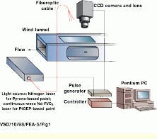
FIGURE 1. In the Air Force research work completed to date on circular and elliptical injectors that exhaust perpendicularly into a supersonic freestream at Mach 2 speed, a back-illuminated CCD camera and software from Pixel Vision are helping to acquire images of the fluorescence of pressure-sensitive paints (PSP) applied to the fuel injectors. The corresponding pressure fields provide researchers with valuable temperature and pressure data. The CCD camera, mounted above the supersonic combustion wind-tunnel segment, looks down through a quartz window in the test section that is illuminated by a low-level laser-light source via a fiberoptic cable. This method allows precise illumination of the fuel-injector model.
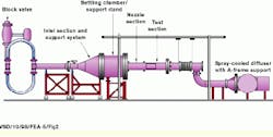
FIGURE 2. A supersonic combustion tunnel facility is being used in US Air Force scramjet experiments to test alternative fuel injector designs. Jet engine research is being conducted by scientists from Wright-Patterson AFB and Innovative Scientific Solutions Inc.
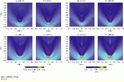
FIGURE 3. Normalized pressure-sensitive paint images of sonic injection are shown for the use of a circular nozzle (left) and an elliptical nozzle (right), both into a supersonic freestream. These color images show the near-field region around the selected injector geometries. Data in these images have been normalized by the freestream static pressure, and the appropriate color bar has been placed beneath each set of images. Regions of normalized static pressure greater than unity appear as light blue/green/yellow; normalized pressure zones below unity are dark blue/purple. The freestream flow direction is from bottom to top, and the jet fluid is flowing out perpendicularly from the plane of the page into the freestream. In Cases C1 to C4 (left), the freestream flow expands around the circular injector until it separates, resulting in a low-pressure wake region. Farther downstream, the flow re-compresses back to the freestream static pressure. In Cases E1 to E4 (right), the wake from an elliptical injector appears comparatively narrow very near the leeward edge of the injector in relation to those in (left), and it remains narrower until recompression begins.