Dual buses empower for French Navy ship
Dual buses empower for French Navy ship
By John Haystead, Contributing Editor
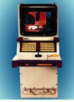
nboard the French Navy`s aircraft carrier Charles De Gaulle, several UNIX-based workstations and off-the-shelf graphics processors are interconnected by two system buses to deliver real-time radar, television (TV), and infrared (IR) imagery with stored tactical data and map overlays on a single display. Part of the ship`s SENIT combat-management system, the Calisto multifunction consoles operate via the VMEbus and the Primabus in numerous modes such as radar and infrared search, weapons control, and system supervision (see Fig. 1).
In addition to situational display, each console can remotely operate all weapons, sensors, and communications equipment, as well as perform diagnostic functions and built-in testing.
Developed and deployed by CS Defense (Paris, France), the Calisto consoles are modular workstations that contain a base UNIX workstation, a VME image-processing unit, and one or two high-resolution, 19-in., 1280 ¥ 1024-pixel color displays. The main UNIX processor is a VMEbus version of the Hewlett-Packard Integrated Systems Division (HP; Palo Alto, CA) HP 9000 Series 700 workstation running the HP-UX operating system with 256 Mbytes of main memory and 2 Gbytes of disk memory.
The HP workstation manages the Calisto system and generates its X-graphics overlays. Display functions include object tracking, picking, clipping, coordinate-systems changes, raster graphics functions, and soft copy. Tactical processing functions are programmed in ADA using a compiler developed by Aonix (San Francisco, CA), whereas the menu-driven man-machine interface is programmed in C language. Programming tools include X11 R5 X-Window and PEX software, MOTIF, and graphical and tactical libraries. Library functions include IR and radar system displays and NATO-symbology track representations.
Varsity system
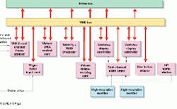
At the core of the Calisto system are the commercial-off-the-shelf-based integrated graphics processor, radar-scan converter, and TV-windows interface developed by Primagraphics (Royston, England). The modular Varsity system is composed of nine VMEbus modules plugged into a dedicated VME32 backplane (see Fig. 2). While interboard and workstation-control information is transferred over the VMEbus, all high-speed data transfers are handled by the system`s secondary multimaster Primabus.
Implemented via VME-P2 connectors, the 60-Mbit/s Primabus is controlled by a Velocity+ double Eurocard controller board with a 30-MHz, AMD29050 RISC processor. Because the Velocity+ does not have its own onboard EPROM, its embedded software is downloaded from the HP workstation at system bootup.
The control system is an embedded Primalib program developed by Primagraphics with a special command interface defined jointly by Primagraphics and CS-Defense. The system is a precursor to Primagraphics` PARIS control system (see "Next-generation radar-image systems,"
p. 47). Commands and data from the workstation are passed to the VMEbus via a bus-to-bus adapter.
Live TV and IR video
The TV and IR video signals are processed by the 6U VME Video Input Module (VIM-2) card. Two channels of asynchronous video (either TV or IR) are digitized to 8-bit monochrome resolution at a sampling rate of 15 MHz. Signals can be zoomed up by a factor of 2 or 4 (horizontal and vertical) or down by factors of 2, 3, 4, or 8 (horizontal only) using hardware on the card itself; vertical zoomdown is handled in software. Specialized hardware on the VIM-2 card also generates up to four real-time video-intensity histograms used to improve the contrast and brightness of the incoming video.
The digitized video data are placed in the VIM-2`s onboard memory (1 Mbyte per channel--enough for a 1k ¥ 1k image) for processing by the Velocity+ RISC processor through one of four software-controlled look-up tables. This processor performs real-time histogram equalization and compresses the data from eight to six or seven bits. Because each line of video input is assigned to a different histogram area, four different contrast enhancement algorithms can be run.
The HP workstation performs additional contrast enhancement using data from the processed histogram of the Velocity+ processor. Says Nick Porter, Primagraphics senior systems consultant, "This ability to perform up to four independent real-time histogram equalizations on different portions of the same image is particularly useful when the correction required to enhance contrast is markedly different on either side of a horizon within the image."
Radar scan conversion
Raw radar video is processed and digitized by the Virgo+ radar interface board (see Fig. 3). Signals are first preprocessed for gain and offset using a programmable high-pass filter and a 256,000 element look-up table, and then digitized to 8-bit precision at
40 MHz. The data are then reduced to four bits using a programmable look-up table and are next processed in both range and azimuth to produce a 2048 ¥ 2048 polar store. If higher range resolution over a shorter swath size is needed, the polar store can be mapped to a subset of the digitized data.
The processed radar data are then transferred over a front-panel interface to the Victory DMA controller card, where they are buffered and passed to the polar image memory store on the Vulcan image-warping card via the Primabus. Here, scan-conversion algorithms map the incoming s-q radar image to the Cartesian coordinates of the display framestore. The Vulcan`s dual-geometry processor ICs perform arbitrary linear or nonlinear image transformations at 3.75 Mpixel/s and are able to update a 2k ¥ 2k resolution display in real time handling a 60-rpm radar-antenna rotation rate.
Because the image is updated in sectors, it gives the appearance of a conventional rotating radar screen. The radar image can also be programmed to smoothly fade out over time to provide target history trails. This image-mapping technique prevents holes in the displayed image and preserves target shapes regardless of range or off-center settings.
Integrated display
After scan conversion, the radar data are written to one or both Venture+ display controllers, obtaining a high-resolution framestore with color-video output and up to 8-bit resolution. The controller(s) integrates the radar data with background maps in a 7-bit combined layer. The maps are drawn by the Velocity+ processor using the Primagraphics` Primalab graphics library.
Video data from the VIM-2 card are also passed to the Venture+ display controllers over the Primabus. Although the controllers are capable of 8-bit resolution, some bits are often used to allow both video and radar to be displayed using the same board. For example, if the display look-up tables for both videos can be shared, then 128 levels (7-bit resolution) are used for the video display. However, if both TV and IR data are being displayed simultaneously, then a 6-bit display with an additional control bit is often used. This technique allows the infrared data to be displayed in pseudo-color, while the TV video is presented in monochrome.
The dual-channel analog video keyer card uses high-speed switching circuits to combine the analog RGB signal from the workstation monitor output with that from the Venture+ controller. The keyer extracts the horizontal and vertical sync information from the workstation display-controller output and generates a pixel clock for the Venture+ controller. The pixel clock signal is passed from the keyer to the Venture+ controller via a front-panel connection. Control software runs on the host workstation via the bus-to-bus adapter, allowing the position and overlap of the radar and video windows to be altered when necessary.
Using a set of software-programmable video thresholds, the overlay and underlay graphics outputs of the workstation`s graphics processor are split into separate palettes with overlay objects given the highest display priority. Because the output from the graphics card and the Venture+ are precisely synchronized, however, whenever the workstation controller output is black, the output from the Venture+ will be displayed instead. Underlay objects are mixed with the radar video so that they become more visible as the radar image fades away.
Open upgrade path
Because the SENIT combat-management system and its Calisto workstations are based on basic commercial processors and standards, they are able to take advantage of next-generation hardware technology as it becomes available without requiring modifications to the overall system software (see Fig. 4). For example, as observed by Porter, "There`s a high degree of software compatibility between the Varsity system and our next-generation CAT system, which can provide higher performance using fewer boards. However, as with all military procurements, long program lead times as opposed to the availability of technology are generally the limiting factors to rapid implementation."
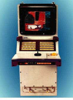
FIGURE 1. Developed by CS Defense (Paris, France) and deployed on the French Navy`s aircraft carrier Charles De Gaulle, Calisto consoles manage and display data from multiple sensors including radar, television, and infrared imagery integrated in real time with X-graphics overlay data generated by a Hewlett-Packard 9000 workstation. The Calisto screen shows a live television image of a helicopter inset against a scan-converted radar plot.
FIGURE 2. As a key structure of the Calisto system, the modular Varsity system comprises nine VMEbus modules plugged into a dedicated VME32 backplane. While interboard and workstation control information is transferred over the VMEbus, all high-speed data transfers are handled by the system`s secondary multimaster Primabus. The 60-Mbit/s Primabus is controlled by a Velocity+ controller board with a 30-MHz, AMD29050 RISC processor.
FIGURE 4. Multiple Calisto consoles are incorporated within the SENIT combat-management system built by DCN International (Paris, France) for the Charles de Gaulle. The SENIT`s open-systems architecture allows next-generation processors to be incorporated without requiring extensive software modifications.
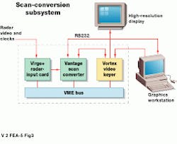
FIGURE 3. The Primagraphics` workstation-based scan converter system allows primary radar video to be added to a UNIX or Windows-NT graphics display. A range of housing options is available including 19-inch rack and desktop enclosures. Control information from the workstation is passed to the scan converter via an RS-232 connection managed by the PARIS software system.
Next-generation radar-image systems
Since the original French Calisto/Varsity system was first developed, Primagraphics (Royston, England) has been able to take advantage of later-generation ICs, memory chips, and field-programmable gate arrays to implement similar capabilities in fewer card slots. For example, a complete radar-scan-conversion system for UNIX (Sun Microsystems` Sparc SunOS and Solaris, Hewlett-Packard HPUX, and Digital Equipment Corp. DEC-UNIX) or Microsoft Windows-NT workstations and PCs can now be implemented in only three VME slots. The system handles multiple channels of either analog or digital data from radar systems with pulse-repetition frequencies up to 35 kHz.
Like the Varsity system, the newer system uses a Virgo+ radar interface board to preprocess and digitize the raw radar video. However, the data are then passed to the Vantage scan-converter card, which also functions as a complete display driver. Incorporating a 40-MHz Motorola MC68030 processor, the card simultaneously performs scan conversion in multiple windows with special logic replicating radar-image fading similar to that seen from a long-persistence phosphor. A display daughterboard provides analog video output via a high-performance Ramdac with up to 256 underlay and 15 overlay colors from a palette of 16 million. The maximum pixel frequency of 200 MHz allows a 72-Hz screen refresh rate at 1600 ¥ 1280 resolution.
A Vortex video keyer synchronizes a Vantage display to the workstation display output. In addition to signal switching, the Vortex keyer allows semi-transparent mixing of images, permitting background graphics to show through less-intense portions of the radar video layer. Variable image transparency is achieved through an analog mixing technique controlled by the brightness of the incoming video. A high-performance phase-locked loop synchronizes the video sources. The system supports up to three video inputs and both interlaced and noninterlaced video outputs at a maximum pixel clock rate of 160 MHz.
Control information from the workstation is passed to the scan converter via an RS-232 client-server protocol using the Primagraphics Advanced Radar Interface Software (PARIS) routines (see Vision Systems Design, Jan. 1998, p. 13) . The Paris system integrates with either X-Window or Windows-NT graphical user interfaces. Several high-level libraries simplify application program development, such as a MOTIF toolkit, while integrated object graphics define maps and symbology in a world coordinate system and are automatically rendered by the graphics library as the view changes.
CAT image processing
Primagraphics` latest-generation CAT image-processing and display system is designed around a family of display and input/output daughterboards. The 6U double-Eurocard CAT motherboard incorporates Texas Instruments` TMS320C80 Multimedia Video RISC processor (MVP), as well as a higher-speed secondary bus (up to 400 Mbit/s transfer rates). Supported by four on-chip DSP processors, the MVP C80 can perform up to two billion operations per second (BOPS) moving 2.4 Gbytes of data and 1.8 Gbytes of instructions per second. A 512-kbyte block of shared SRAM between the VME interface and the processor decouples processor activity from bus activity. The processor also includes 8 Mbytes of synchronous DRAM, 1 Mbyte of EPROM memory, and four serial channels for keyboard, mouse control, and general input/output.
Two application and one display daughterboard sites connect directly to the C80 processor`s extended bus for up to 200-Mbit/s data-access rates. A VME P2 header connector also allows VME-P2 bus-adapter daughterboards to be developed. External control is via a VME64 interface. Application daughterboards include the Leopard video input board, which accommodates multiple video inputs at a programmable 8-bit/color sampling rate up to 60 MHz, and the "Jaguar" radar input daughterboard that accepts data from the Virgo family of radar digitizer boards.
As opposed to the Calisto system, the CAT display daughterboards support multilayer 24-bit display at resolutions to 1600 ¥ 1280 (Lion board) or 2048 ¥ 2048 (Tiger board).
The CAT display architecture allows additional functions to be handled in software rather than dedicated hardware. J. H.


