Manufacturing by Touch
Testing touch probes for repeatability requires a high-precision vision system based on CMOS camera, frame grabber, software, and novel lighting design
Sleek, integrated designs have become fashionable for so-called “seamless” cell phones, and other consumer electronics products may follow soon. These designs require very tight manufacturing tolerances, which in turn create a need for touch probes that perform in a precise and predictable way. One leading probe maker has turned to Confero Solutions for a system that tests for probe reset repeatability in machining applications requiring very high precision. The company says it can calculate probe position to within 0.005 µm by locating the probe’s tip using normalized cross correlation.
Confero is a 2006 startup specializing in turnkey sensing and motion-control systems for the metrology, life-sciences, semiconductor, machine-tools, and general manufacturing industries. Says Brent Bartlett, imaging engineer at the company, “The demand for parts with extremely precise dimensions has increased in many areas. Cell phones, for example, need their plastic housings to fit to within tens of microns to form the smooth joints and seals that we see today. This means that the machines used to create them must be controlled to within a few microns.”
Elsewhere, high-precision machining is in greater and greater demand, especially in the automotive and semiconductor industries. “The tolerances for moving components in the engine such as cylinders must be as tight as possible,” Bartlett says, “and when fabricating microelectromechanical-system devices or semiconductors, the dimensions of the physical components of the machine must be made with extremely tight tolerances.”
The Confero test system targets one particular characteristic of touch probes that is critical to repeatability: “resetability,” which measures how closely a test probe comes to returning to its original orientation after being displaced by contact with the object it has just sensed. Ironically, Confero’s test system does not measure the location of a touch probe by touching it; rather, it takes its measurements optically from a distance, says Bartlett, so as not to mechanically influence the results.
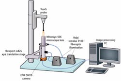
The Confero touch-probe measurement system consists of several parts: the PC system that analyzes captured images and interfaces with the human operator; the imaging subsystem that captures and delivers those images; the lighting subsystem that enables fine-detail capture; and the rigid post and other mechanical structures on which certain parts of system are mounted (see Fig. 1).
At the bottom of the post resides an x-y-z translation stage, specifically an m426 from Newport. This is used for manually positioning the camera and associated optical devices to bring the touch probe into focus. The probe under test, in turn, resides at the top of the post on a fixture. That fixture contains the magnetic or mechanical mechanism responsible for performing the touch-probe reset.
Utilizing a pair of Intralux 5100 illuminators from Volpi, the imaging subsystem in Confero’s tester combines a Silicon Video 5M10 CMOS camera from EPIX with a 50x microscope objective from Mitutoyo, a 1x Navitar optical coupler, and a ringlight (see Fig. 2).
The host PC is a Dell machine based on a dual-core Intel processor with 2 Gbytes of DRAM, running the Windows XP operating system and equipped with the conventional complement of peripherals, including disk drives, monitor, keyboard, and mouse. It incorporates a Model PXCI SI digital frame-grabber board from EPIX in a PCI slot in the PC’s motherboard. Confero used LabView from National Instruments as the software test platform.
Because the expansion/contraction of materials due to temperature change will have an effect on probe characteristics, Confero equipped its host system with a temperature-monitoring subsystem. Thus, if room temperature rises or falls outside certain limits, the test data for that period of time will be discarded.
The Silicon Video 5M10 is a monochrome, 5-Mpixel, progressive-scan camera based on a CMOS sensor and featuring low-noise digital signaling. It’s a compact device, measuring 1.91 × 1.51 × 0.74 in. and weighing 2.6 oz, and it interfaces to a frame-grabber board with a single shielded cable that provides power, a programmable pixel clock, control signals, and a video interface. The interface, a proprietary one based on low-voltage differential signaling (LVDS).
The camera’s pixel clock and frame rate are slowed to prevent overrunning the PC’s PCI bus—a 33-MHz, 32-bit bus with a theoretical maximum data-transfer capability of 132 Mbytes/s. Capable of capturing 12 to 15 frames/s, the camera is used at a 6-frames/s rate in the Confero configuration.
The 5M10 contains a MT9P001 sensor from Micron Technology, a 5.70 × 4.28-mm CMOS device featuring an electronic rolling shutter for maximum frame rate and a global-reset-release shutter. Other sensor features include windowing, column and row skip modes, snapshot mode, 12-bit dynamic range, and an active programmable array resolution of 2592 × 1944 square pixels, each measuring 2.2 × 2.2 µm.
The coupler, which contains a beam-splitter, is a Model 1-62840 from Navitar’s Ultra Precise Eye Body Tubes, which are designed for infinity-corrected microscope objectives in high-magnification, high-resolution imaging. The objective is a x50 device that’s part of the Mitutoyo 378 Series. These are infinite-tube objectives supporting what the manufacturer claims is “the world’s largest working distance.” The same objective is used in Mitutoyo’s own FS-110 metallurgical microscopes for inspecting microcomponents such as ICs and video head parts.
Putting it all together
Probes under test can be affected by temperature changes, so Confero eliminated temperature as a variable, toggling the camera on and then off after every image capture event. The rationale here is to minimize the time during which the camera is operating and, thus, reduce the thermal effects caused by heating of the camera housing.
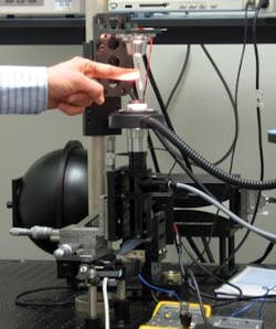
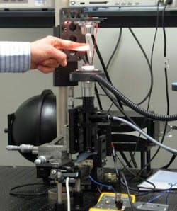
In operation, a human operator pokes the probe tip of the Confero system, simulating the effect of its coming into contact with an object in a production environment. The probe then settles back to its original position, and the EPIX 5M10 captures an image of the probe. The camera is triggered to take a picture either by Labview after a prescribed time interval or by the operator by clicking on a screen button. One challenge, Bartlett explains, was to capture enough spatial information to provide a meaningful image “at this high level of magnification.” This the company accomplished with a dual lighting approach: axial and ring.
Lighting is provided to the touch-probe test system by two Volpi Intralux 5100 systems. These 215 × 120 × 200-mm boxes each contain a 150-W halogen reflector lamp delivering up to approximately 12.3 Mlux of light to a fiberoptic lightguide that feeds into the Confero optics. The light from one of the Volpi systems terminates inside the Navitar coupler, where it hits a beamsplitter that reflects it up as axial light toward the touch probe. Light from the other illuminator travels to a ringlight mounted around the outside of the Mitutoyo objective and then upwards in a 360º continuous ring toward the probe.
To calibrate the Confero system, the axial light is turned on first to assist the human operator in locating the narrow tip of a touch probe; then the ringlight is turned on to illuminate the wider “shoulders” at the top of the probe. The tip of the probe, easier to focus on than the shoulders at this high level of magnification, provides a reference point from which “it’s pretty easy to move the focus up to the ring to run the algorithm,” Bartlett says. An image of the shoulders is then captured, appearing as a ring of light that’s used to determine how accurately a touch probe resets and doing so with a high tolerance for focus change.
“If the camera system were focused on a relatively flat surface,” Bartlett explains, “the image would go out of focus pretty quickly if the system drifts up or down. But by focusing on a relatively large, curved surface, the reflected ring of light won’t change much.”
Before putting the system to work collecting data on touch-probe reset accuracy, Confero ran it for about a half hour to establish a baseline noise level and determine the stability of the system over time. An image of the ringlight was captured and then processed by the PC to minimize background effects and noise. Subsequent images were captured every 15 s for about 40 minutes and compared through normalized cross correlation to locate the ring. System noise, Bartlett reports, was found to be on the order of 0.02 µm. Here, “noise” refers to the average distance from the mean reset location.
“The cross-correlation algorithm used to calculate probe position is reliable at one-quarter-pixel resolution,” Bartlett says. “Since the system has an effective pixel size of 0.044 μm (because of the 50X magnification factor), the position can be recorded to within 0.011 μm,” he adds, “we also uses a few other “image-processing tricks” to minimize background noise and sharpen images.
Devices under test
At this stage of development, Confero relies on a human operator to displace the probe tip and a human finger to emulate the object that is going to be machined in a production environment. The probe tip is typically displaced and, after settling, its position is measured, with each test consisting of about 30 iterations. The company is considering automating the displacement process and increasing the number of displacements per test.
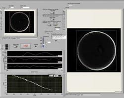
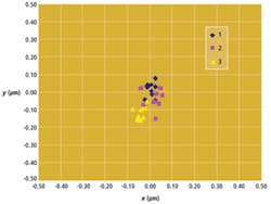
The user interface for this process was developed using Labview 8.5, which, Bartlett says, allows for easy visualization and control of the camera and timing systems (see Fig. 3). Confero tested a touch probe in three different fixtures, displacing the probe tip 30 times in three random directions, with the axes of movement defined by the fixturing. The relative effectiveness of each fixture for high-precision reset was readily apparent from the test results.
In Fixture A, for example, the reset location of the probe tip strayed as far as 0.60 µm from the original position after some displacements, and the amount of reset dislocation varied widely—a disincentive where high-precision positioning is concerned. Fixture B demonstrated consistent reset error of about +0.10/-0.20 µm in the y dimension and ±0.10 µm in the x dimension (see Fig. 4). That’s precision—both in reset positioning and in the measurement of that positioning.
null
